Input Amplifiers
The input amplifiers for Channel A and Channel B are identi-
cal. A trigger level circuit belongs to each amplifier. The trig-
ger level is adjusted to match the hardware during the voltage
calibration procedure, see Chapter 7. Note that the input am-
plifiers must be adjusted according to Chapter 7 (step re-
sponse, sensitivity etc). The description refers to both chan-
nels (Channel B information within parentheses).
Recall the timer/counter default setting. Select the measure
-
ment function Time A-B. Set both input channels to DC, Man
Trig = 0.000 V. No signals connected.
The RF shield must be removed before measuring on the input
amplifi e rs. It is soldered to two of the shield clips. Don't forget
to put the shield back afterwards and secure it by resoldering.
First measure some DC values. U3 pin 9 (pin 13) should be
near 0.000 V. The same applies to the trigger level, U3 pin 10
(pin 12). The voltage to ground at the point where R171
(R243) and R172 (R244) are connected should be approxi
-
mately -0.8 V.
Connect a 1 kHz square wave with amplitude 1 V
pp
in1MW to
Input A (Input B). Measure at the following points (see also
figure cc) and use the ground pads that are distri buted over the
PC board:
Test Points Approximate Voltage
R140 to R141 (R212 to R213) 1.00 V
pp
R156 to C109 (R229 to C140) 0.40 V
pp
U1 pin 2 (U2 pin 2) 0.20 V
pp
U1 pin 3 (U2 pin 3) 0.20 V
pp
U1 pin 6 (U2 pin 6) -1.00 V
dc
R151 to R157 (R223 to R230) 0.40 V
pp
U3 pin 9 (U3 pin 13) 0.40 V
pp
R309 and R314 (R313 and R315) ECL levels -1.0 V and -1.7 V
R301 both sides (R304 both sides) LVPECL levels 1.6 V and
2.6 V
Test the trigger level by manually setting the following trigger
levels. Check the voltage at X6 (X7) and U3 pin 10 (pin 12).
Set Level Approximate Voltage
+1 V +0.41 V
+4 V +1.65 V
-4 V -1.65 V
-1 V -0.41 V
Set the timer/counter to default. Select the measuring function
single period. Connect the 1 kHz square wave to channel A
(B). Measure with oscilloscope at X6 (X7). See figure dd for a
typical signal.
If any repair work has been done on the input ampl ifiers, both
adjustment and voltage calibration must be performed after
-
wards. If any repair work has been done on the trigger level
circuits, at least voltage calibration must be performed after
-
wards. See Chapter 7.
6-8 Troubleshooting
+5VU
+5VU
+5VU
OFFCTRL
ONCTRL
ON
OF F
C389
100NF
C389
100NF
R593
1K
R593
1K
R592
1K
R592
1K
R449
10K
R449
10K
X51X51
Q58
BC847B
Q58
BC847B
X22X22
X50X50
VCC
14
GND
7
U29C
LVC74A
U29C
LVC74A
R479
220
R479
220
C197
100NF
C197
100NF
R466
1K
R466
1K
X24X24
Q47
BC847B
Q47
BC847B
R472
47
R472
47
X23X23
R453
1K
R453
1K
1M
R478
1M
R478
R584
47
R584
47
D
2
CLK
3
S
4
R
1
Q
5
Q
6
U29A
LVC74A
U29A
LVC74A
R480
470
R480
470
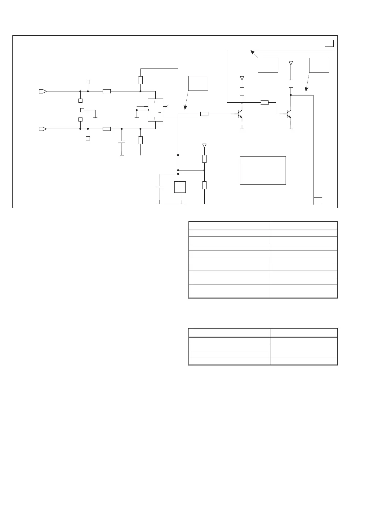
Figure 6-6 ON/OFF logic
ON H
OFF L
ON H
OFF L
ON L
OFF H
A & B are control
signals to PSU
switches and
dummy load.
POWER-ON RESET CKT
A
B