Timebase Reference
Circuits
The measurement reference is either a 10 MHz signal from an
internal oscillator (standard crystal oscillator or optional
oven-controlled crystal oscillator) on the main circuit board or
a signal from the external reference input that accepts the fol
-
lowing frequencies: 1, 5 and 10 MHz. A frequency multiplier
transforms the external signal to 10 MHz. The selected 10
MHz reference is always available at the internal reference
output. See Figure 6-14.
The main PCB is prepared for both types of internal timebase,
but only one of them is mounted. The selection is made at the
factory. You have to run the utility program (see page 5-3), if
the oscillator is to be ch a n g ed. Closed Case Calibratio n is
used for adjusting the oscillator. On power-up the processor
outputs the setting that is stored as the co rrect on e fo r
10.000000 MHz. It will take some time for the oven oscillator
to reach the correct frequency. A calibration must be
performed if the adjusting volt age should move during opera
-
tion, not only on power-up.
The selection between the on board oscillator and the external
reference is made in the FPGA. The 10 MHz signal from the
other source is switched off.
Connect a 10 MHz signal to the external reference input. Use
the
SETTINGS menu to alternate between internal and exter
-
nal oscillator. Check for correct signals at U4:6 for the stan-
dard oscillator, at U4:8 for ther oven oscillator and at U33:3
for the external reference. Check also that the selected
timebase reference is present at the internal reference output
BNC connector on the rear panel.
Standard Oscillator
See Figure 6-14 and Figure 6-16.
The control signal (U4:1) must be high. The frequency is con
-
trolled by a PWM signal from the processor. After filtering
the resulting DC voltage changes the capacitance of D24. A
DC level between 0 V and +3.3 V at R289 should somewhere
within the adjustment range give 10.000000 MHz. Check the
output signal and frequency at U4:6.
If the standard oscillator is repaired, a new calibration must be
performed. See Chapter 7. A new f actory calibration b y
means of the utility program should also be performed.
Optional Oven Oscillator
See Figure 6-14, Figure 6-15 and Figure 6-16.
The oven oscillator is a self-contained un it, enclosed in a
metal box and soldered to the mai n circuit board. It cannot be
repaired and must be replaced with a new oscillator if it is
faulty.
Let the oven oscillator warm up 10 minutes b efo re starting
measurements. The 12 V supply voltage can be checked at
6-12 Troubleshooting
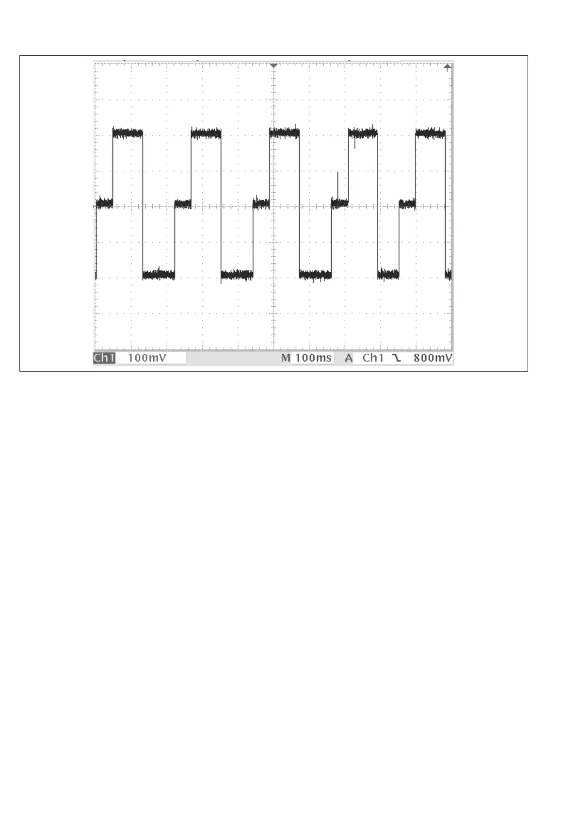
Figure 6-13 Oscillogram showing the signal at X7, Period Single B.