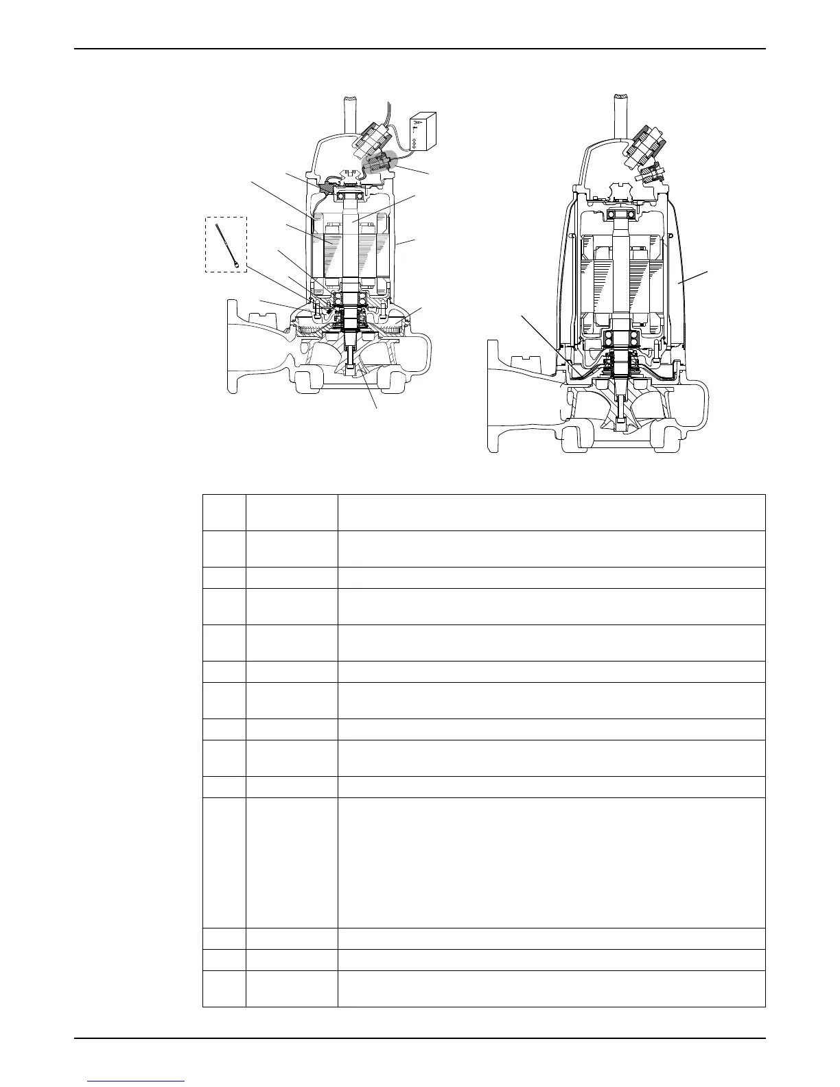
Parts
1
11
10
9
8
7
2
3
6
12
13
14
WS000850A
Figure 1: Without cooling jacket
Figure 2: With cooling jacket
Positio
n
Denomination Description
1 Monitoring
sensor
Optional sensor. For information about sensors, see Monitoring equipment (page
13).
2 Shaft Stainless steel, with an integrated rotor
3 Cooling without
jacket
The pump is cooled by the ambient liquid.
4 Cooling with
jacket
The motor is cooled by a closed loop system. An integrated coolant pump circulates the
coolant whenever the pump is operated.
5 Flow diffuser Provides heat transfer from the coolant to the pumped fluid.
6 Seal housing Includes a coolant that lubricates and cools the seals; the housing acts as a buffer
between the pumped fluid and the electric motor
7 Impeller N-impeller, a semi-open, two-vane impeller
8 Inspection
chamber
Equipped with an FLS10 leakage sensor to prevent damages to the motor
9 FLS10
For information about FLS10, see Monitoring equipment (page 13).
10 Mechanical seals Made of one of the following alternatives:
• Alternative 1
• Inner seal: corrosion-resistant cemented carbide WCCR/WCCR
• Outer seal: corrosion-resistant cemented carbide WCCR/WCCR
• Alternative 2
• Inner seal: corrosion-resistant cemented carbide WCCR/WCCR
• Outer seal: silicon carbide RSiC/RSiC
11 Main bearings Consisting of a two-row angular contact ball bearing
12 Motor
For information about the motor, see Motor data (page 67).
13 Thermal contact/
Thermistors
For information about the thermal contact and thermistors, see Monitoring
equipment (page 13).
Product Description
12 Flygt 3202 Installation, Operation, and Maintenance Manual