1. If thermal contacts are included in the pump installation, then connect the T1 and T2
control conductors to the MiniCAS II monitoring equipment.
NOTICE:
Ex-approved products must always have the thermal contacts connected irrespective
of the ambient temperature.
2. If thermistors are included in the pump installation, and screened or auxiliary cable is
used, then connect T1(1) and T2(2) to the thermistor relay or MAS 711, and T3(3) and
T4 (4) to MiniCAS II or MAS 711.
3. If the pump is prepared for MAS, then the separate sensor connection unit in the
pump is connected via SUBCAB 12×1.5 according to Connection to the monitoring
equipment (page 37).
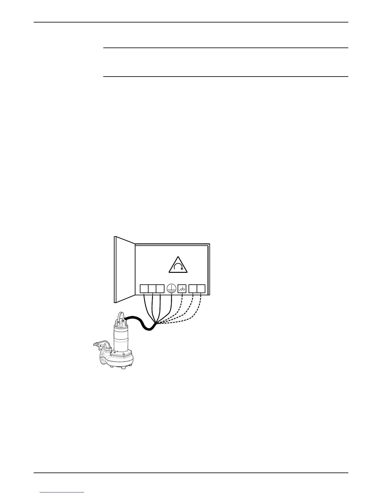
4. Connect the mains leads (L1, L2, L3, and ground (earth)) to the starter equipment.
For information about the phase sequence and the color codes of the leads, see
Cable charts (page 26).
5. Check the functionality of the monitoring equipment:
a) Check that the signals and the tripping function work properly.
b) Check that the relays, lamps, fuses, and connections are intact.
Replace any defective equipment.
Cable charts
Description
This topic contains general connection information. It also provides cable charts that show
connection alternatives for use with different cables and power supply.
L2
L1 L2 L3
L3L1
WS000509B
WS000509C
L2
L3L1
L1
L3L2
T1
T2
Figure 9: Phase sequence
Connection locations
The figures in this section illustrate how to interpret the connection strip symbols.
Installation
26 Flygt 3202 Installation, Operation, and Maintenance Manual