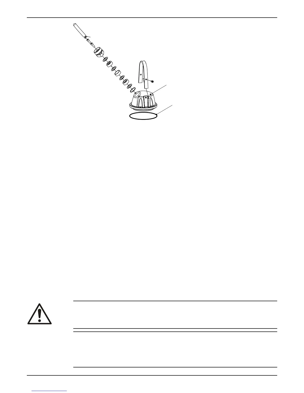
1. Entrance cover
2. O-ring
For more information about the cable entry, see the Parts list.
1. Remove the entrance cover and the O-ring from the stator housing.
This provides access to the terminal board.
2. Check the data plate to see which connections are required for the power supply.
3. Arrange the connections on the terminal board in accordance with the required
power supply.
Links (jumper strips) are not used with the Y/D start.
4. Connect the mains leads (L1, L2, L3, and earth (ground)) according to applicable
cable chart.
The earth (ground) lead must be120 mm (4.8 in.) longer than the phase leads in the
junction box of the unit.
5. Make sure that the pump is correctly connected to earth (ground).
6. Connect the control leads to the applicable terminal board.
7. Make sure that any thermal contacts incorporated in the pump are properly
connected to the terminal board.
8. Install the entrance cover and the O-ring on the stator housing.
9. Fasten the screws on the entrance
flange so that the cable insertion assembly bottoms
out.
Connect the motor cable to the starter and monitoring equipment
If there are two power cables, then the cable that is connected to T1 and T2 is labeled. If a
separate control cable is used, then the control leads in the power cable are never
connected.
WARNING:
Do not install the starter equipment in an explosive zone or in the sump.
NOTICE:
• Either thermal contacts or thermistors are incorporated in the pump.
• Thermal contacts must never be exposed to voltages higher than 250 V, breaking
current maximum 4 A. It is recommended that they are connected to 24 V over
separate fuses to protect other automatic equipment.
Installation
Flygt 3202 Installation, Operation, and Maintenance Manual 25