• If using a cable which has been used before, a short piece must be peeled off when
refitting it so that the cable entry seal sleeve does not close around the cable at the
same point again. If the outer sheath of the cable is damaged, then replace the cable.
Contact a local sales and service representative.
• The voltage drop in long cables must be taken into account. The drive unit’s rated
voltage is the voltage measured at the cable connection point in the pump.
• The screened cable must be used according to the European CE requirements if a
Variable Frequency Drive (VFD) is used. For more information, contact your local sales
and service representative (VFD-supplier).
• For SUBCAB
™
cables, the twisted pair copper foil must be trimmed.
Earthing (Grounding)
Electrical Hazard:
• You must earth (ground) all electrical equipment. This applies to the pump
equipment, the driver, and any monitoring equipment. Test the earth (ground) lead to
verify that it is connected correctly.
• If the motor cable is jerked loose by mistake, the earth (ground) conductor should be
the last conductor to come loose from its terminal. Make sure that the earth (ground)
conductor is longer than the phase conductors. This applies to both ends of the motor
cable.
• Risk of electrical shock or burn. You must connect an additional earth- (ground-) fault
protection device to the earthed (grounded) connectors if persons are likely to come
into physical contact with the pump or pumped liquids.
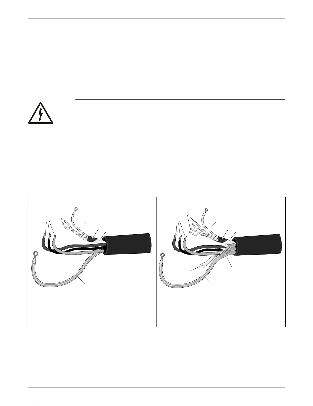
Prepare the SUBCAB
™
cables
This section applies to SUBCAB cables with twisted-pair control cores.
The prepared SUBCAB
™
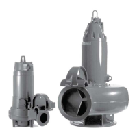
cable The prepared screened SUBCAB
™
cable
SUBCAB 1000V
T
1
T
2
WS004299C
2
3
4
5
1
6
1. T1+T2 twisted pairs in control element
2. Drain wire in control element (bare copper wire)
3. Screened copper pt-foil
4. Insulation jacket/sheath for control element
5. Power cores
6. Earth (ground) core
T
4
T
3
Screened SUBCAB
T
1
T
2
2
3
4
1
5
8
6
7
WS004298B
1. T1+T2 and T3+T4 twisted pairs in control element
2. Drain wire in control element (bare copper wire)
3. Screened copper pt-foil
4. Insulation jacket/sheath for control element
5. Power cores
6. Aluminum foil
7. Earth (ground) core with green/yellow shrink hose
8. Uncovered screen/braided wire
1. Peel off the outer sheath at the end of the cable.
2. Prepare the control element:
a) Peel the sheath (if applicable) and the copper foil.
The copper foil is a screen and is conductive. Do not peel more than necessary,
and remove the peeled foil.
Installation
Flygt 3202 Installation, Operation, and Maintenance Manual 23