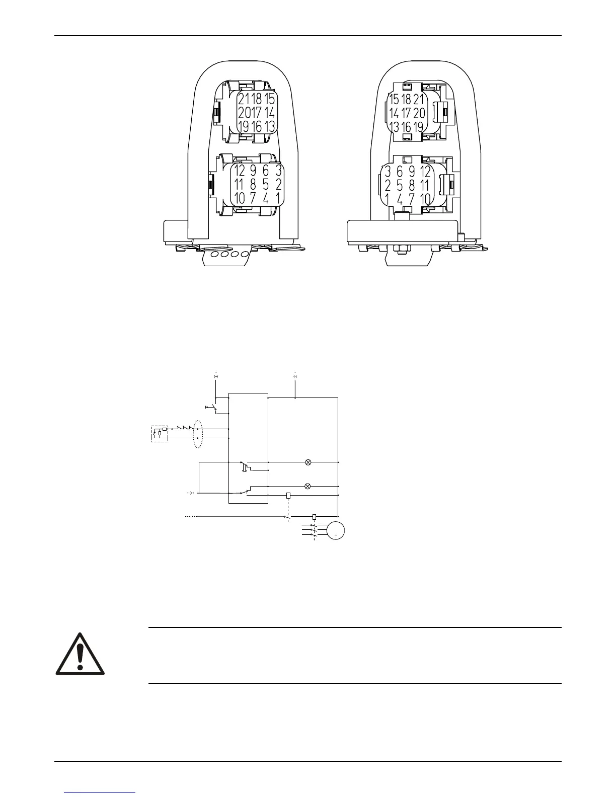
1. Electric connection, sensor cables
2. Electric connection, 12-lead cable
Figure 23: Pin setting connector unit
Connection to the monitoring equipment
MiniCAS II
24 V AC/DC
R
CC
P
C
L2
L1
102
6
7 +T1
T15
T2
FLS10
5 -
11
1
12 VDC
9
8
10S
4
3
WS002623B
C
Pump contactor
CC Control circuit
L1 Caution light (leakage)
L2 Caution light (stator over-temperature)
P Pump main supply
R Reset switch
MAS 711
For information on how to connect to MAS 711, see MAS 711 Installation and Operation
manual.
Check the impeller rotation
WARNING:
The starting jerk can be powerful.
1. Start the motor.
2. Stop the motor after a few seconds.
3. Check that the impeller rotates according to this illustration.
Installation
Flygt 3202 Installation, Operation, and Maintenance Manual 37