WS003892B
Conn. for MAS 711,VIS 10 option
Connection leads
Control leads
MAS
SUBCAB
FLS 10
BN 1
1
1
1
BN 2
2
17
2
2
16
RD 3
Main bearing
WH 3
3
3
3
8
PT 100
4
4
4
4
TC
YE 5
5
5
5
1
YE 6
6
6
6
2
BU 9
VIS 10
7
7
7
BN 2
8
15
8
8
3
RD 19
9
9
9
Stator winding
PT 100 (Phase 1)
WH 4
38
10
10
10
37
RS485 B GY 74
Pump memory
RS485 A YE 75
11
11
11
12
12
12
36
Ground BK 76
35
12V+ RD 77
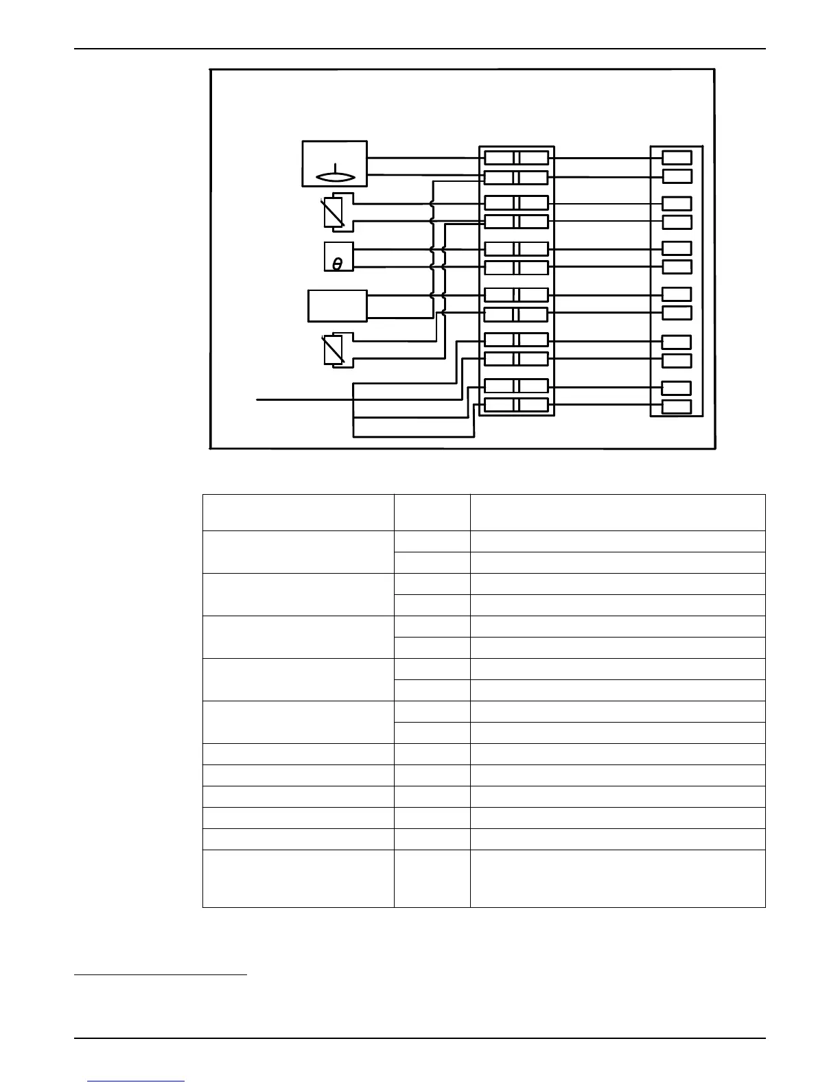
Figure 22: Connection for MAS 711, VIS 10 option
Sensor/Component Sensor cable,
no
3
Base unit terminal block, no
FLS 10 — Leakage in inspection
chamber
1 17
2 16
Pt 100 — Temperature measurement,
main bearing
3 8
4 4
Thermal switches — Temperature
guard stator windings
5 1
6 2
VIS 10 — Vibration sensor
4
7 18
-2 -16
Pt 100 — Temperature measurement,
stator winding ph 1
8 3
-4 -4
Pump memory:
RS–485 B 9 38
RS-485 A 10 37
Supply, ground 11 36
Supply, 12V + 12 35
(Screen) If applicable, attach screen to ground terminals in the
• pump top, and
• electrical cabinet
3
If the sensor cable contains a green-yellow lead, that lead should not be connected.
4
VIS 10 is not applicable to pump type 3153
5
Communication port 37-38 for RS-485 is common to both pump memory and operator panel.
Installation
36 Flygt 3202 Installation, Operation, and Maintenance Manual