10
Installation and Operation Manual
SystemsSystems
2001 and 2002
PLUMBING COMPONENT INSTALLATION
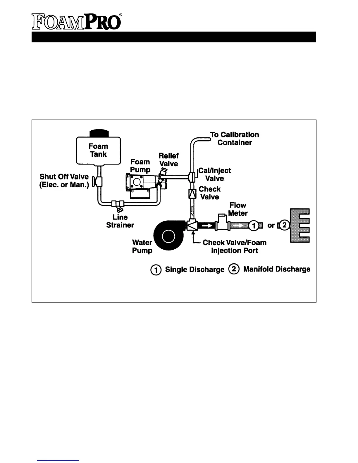
The following diagram (Figure 3) provides recommended guidelines for the location of the system
components that handle water, foam concentrate and foam solution. Note that additional options
such as dual tank systems, multiple flowmeters, etc., are covered by individual manuals included
with those systems; consider potential interferences.
Figure 3. FoamPro 2001/2002 System Piping
A. FOAM PUMP/MOTOR BASE ASSEMBLY
The foam pump/motor base assembly must be
mounted in a horizontal position (See Figure 5).
The base of the foam pump must be anchored
to a surface or structure that is rigid and of
adequate strength to withstand the vibration and
stresses of apparatus operation. Figure 4
provides the mounting dimensions for the
FoamPro 2001 and 2002 foam pump/motor
base assembly. It is required to use flexible
hose when making the hose connections to the
FoamPro 2001 and 2002. DO NOT hard pipe
the system.
Position the foam pump so the circuit breaker/
on-off switch is easily accessible. Also,
consider access requirements for checking and
changing the oil in the crankcase of the foam
pump. Be sure the foam concentrate hoses can
be properly routed to the inlets and outlets on
the foam pump. Foam concentrate should
gravity feed to the foam pump inlet from the
foam tank(s). The foam pump/motor base
assembly must be mounted in an area to avoid
excessive exhaust system heat buildup.
Protect the hoses and wiring from chafing and
abrasion during operation of the foam system.
Protect the foam pump base unit from excessive
road spray and debris. Although the system is
sealed and designed to be resistant to the harsh
environment of fire fighting apparatus, a
6