15
Installation and Operation Manual
SystemsSystems
2001 and 2002
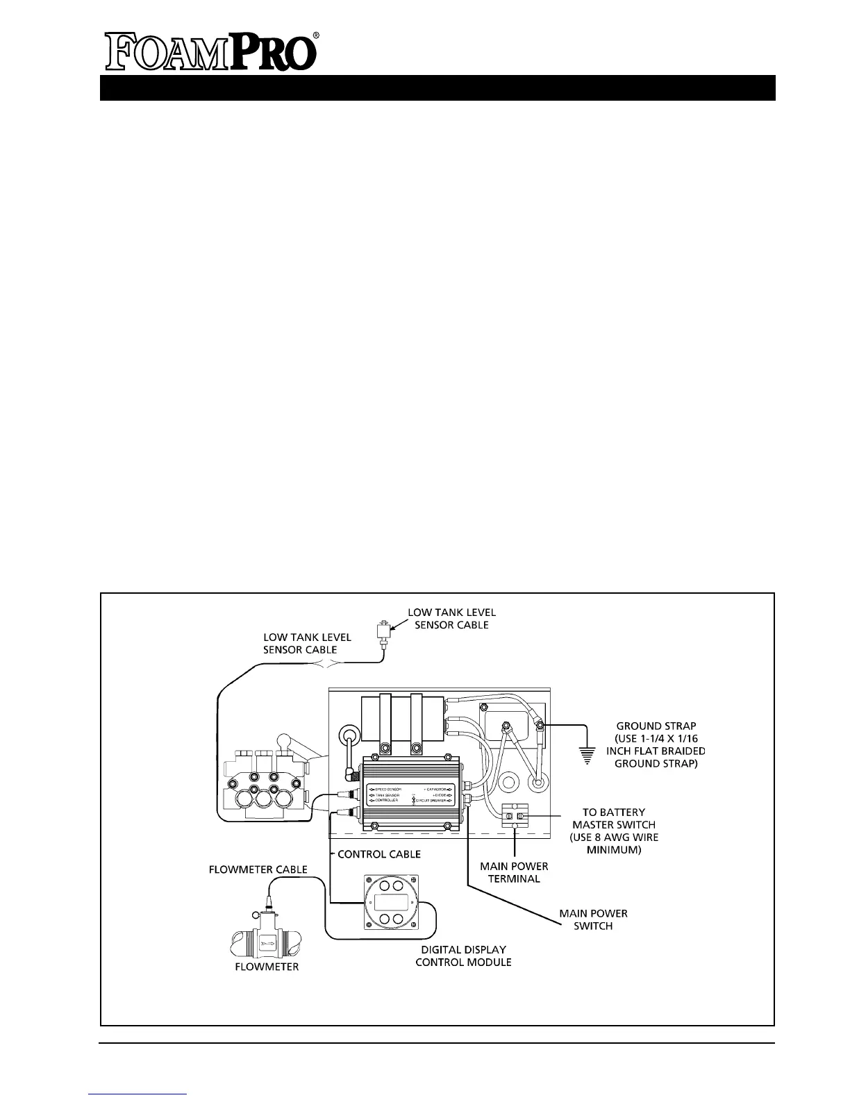
ELECTRICAL CONNECTIONS
Follow the system electrical diagram (Figures 13
and 14) for proper hookup of each of the
electrical components. Complete molded cable
sets are provided with each FoamPro system to
make all the necessary connections. The
cables are color coded and “indexed” so they
only go in the correct receptacle and they can
only go in one way. DO NOT FORCE
MISMATCHED CONNECTIONS.
The system
can only perform when the electrical connections
are sound, so make sure each one is right.
SOME THINGS TO KEEP IN MIND
• DO NOT hook up the main power cables until all
connections are made to each of the electrical
components. The last connection should be the
power cable to the foam pump/motor base
assembly.
ELECTRICAL EQUIPMENT INSTALLATION
Figure 13. FoamPro 2002 Electrical Wiring Diagram
• WARNING: This system contains a capacitor
on the input power. Connect the leads with
the battery off or disconnected. Current will
flow even with the master circuit breaker off.
• DO NOT cut molded cables.
• Provide at least the following amounts of
electrical power from the battery to the main
power terminal:
2001 requires 41 amps;
2002 requires 56 amps;
2001/24 requires 22 amps;
2002/24 requires 30 amps.
Use 8 AWG (minimum) wire directly to the
battery or battery master disconnect switch.
• The S105-2001, S105-2002 and S105-
2002HP systems are designed for 12-volt,
negative-ground systems only. The S205-
2001, S205-2002 and S205-2002HP systems
are designed for 24-volt, negative-ground
systems only.
7
HYPRO