16
Installation and Operation Manual
SystemsSystems
2001 and 2002
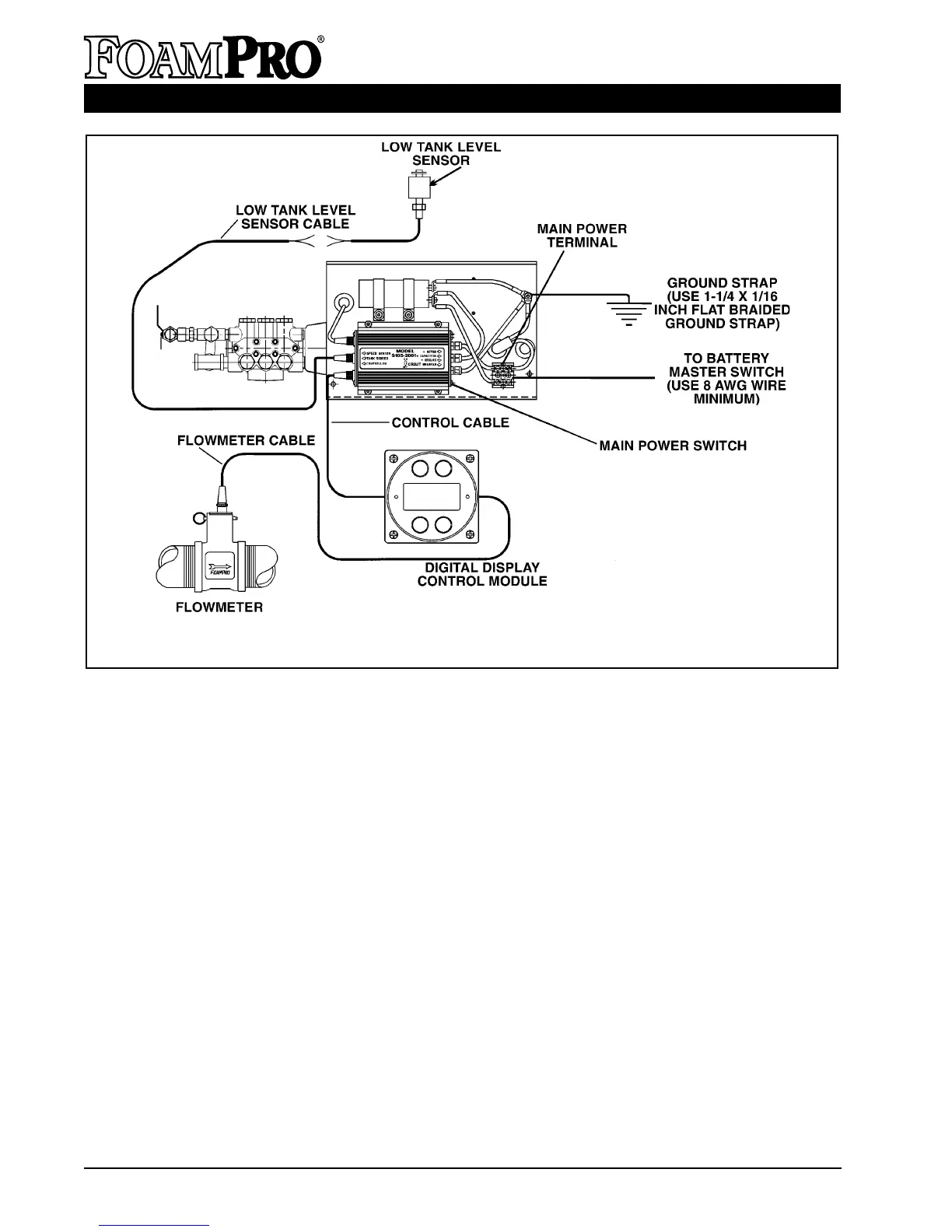
Figure 14. FoamPro 2001 Electrical Wiring Diagram
• Do not mount radio transmitter or transmitter
cables in direct or close contact with the
FoamPro unit.
• Use care when installing molded cables.
Count pins or check color codes before
connecting. Bent pins caused by improper
hookup can prevent proper operation even
when cables are reattached properly.
• Before connecting the molded cables,
inspect the yellow seal washer in the female
connector. If the seal washer is missing or
damaged, water can enter the connector and
cause corrosion of the pins and terminals
that will cause system failure.
• CAUTION: The cables shipped with each
FoamPro unit are tested at the factory with
that unit. Improper handling and forcing
connections can damage these cables,
which could result in other system damage.
• CAUTION: Always disconnect the ground
straps and control cables from the Digital
Display Control Module or other FoamPro
equipment before electric arc welding at any
point on the apparatus. Failure to do so will
result in a power surge through the unit that
could cause irreparable damage to the
display or other system components.
A. DIGITAL DISPLAY/CONTROL MODULE
The Digital Display Control Module is designed
to be mounted in the operator panel of the
apparatus. The cutout that will be needed in the
operator panel is a 3-
7
/8 inch [98 mm] diameter
hole (the same as a 3-
1
/2 inch [89 mm] pressure
gauge). The display is secured with four #10
socket head screws in the four holes in the face
(See Page 40 for a mounting template). The
display requires 5 inches [127 mm] minimum
from the back of the operator panel to clear
HYPRO