17
Installation and Operation Manual
SystemsSystems
2001 and 2002
Figure 16. Motor Driver Box Connections
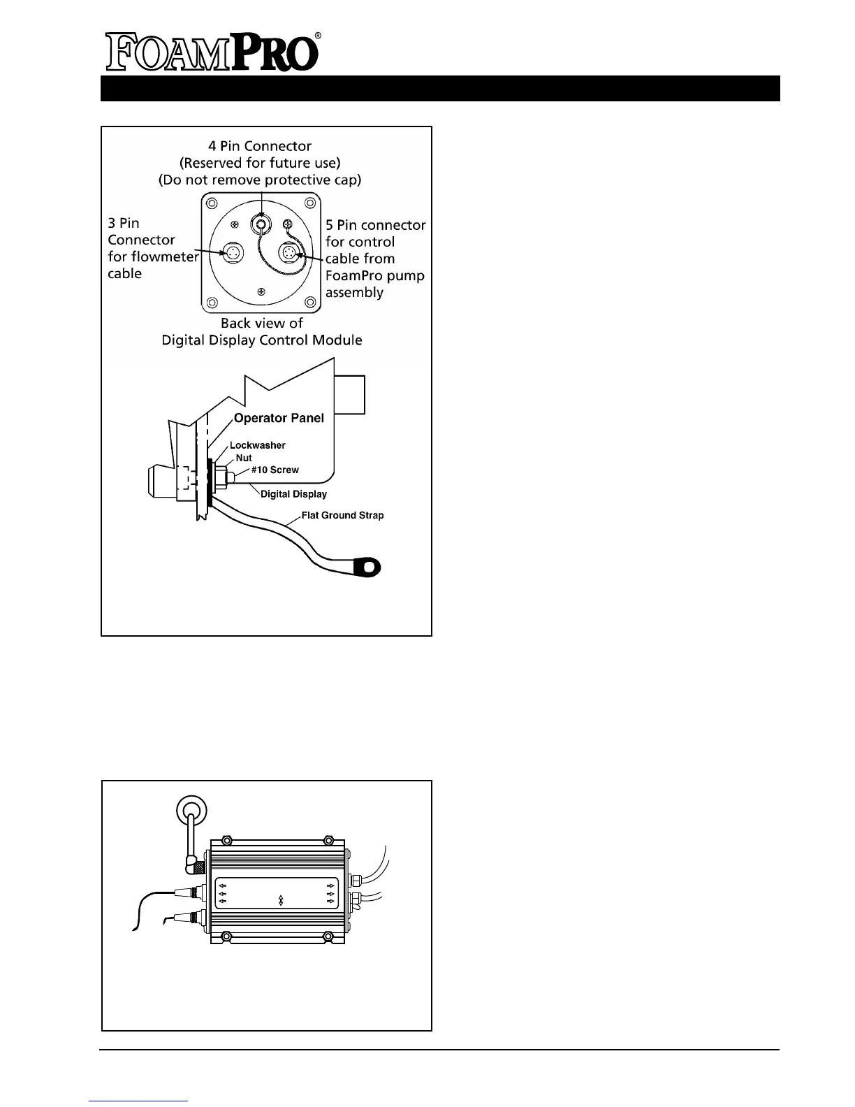
Figure 15. Digital Display Control
Module Cable Connections and
Grounding
SPEED SENSOR
TANK SENSOR
CONTROLLER
CAPACITOR
DIODE
CIRCUIT BREAKER
ON
OFF
+
+
* Connections to be made
during installation.
*
*
wires and connectors. Make sure there is
enough clearance behind the operator’s panel
for the cables. Once the Digital Display Control
Module is mounted, connect the control cable
(red coded cable end) from the motor driver box
terminal to the 5 pin connector on the back of
the Digital Display Control Module (see
Figure 15). A color coded decal on the motor
driver box identifies each cable connection (see
Figure 16).
NOTE: Make sure the panel where the Digital
Display Control Module is mounted has an
adequate ground. For stainless steel and vinyl
coated panels, a flat ground strap must be
attached from one of the four screws holding
the Digital Display Control Module in place, to
the frame of the fire truck to ensure adequate
grounding (see Figure 15).
B. FLOWMETER(s) CONNECTIONS
FOAMPRO FLOWMETER
If a single FoamPro paddlewheel type flowmeter
is to be used, a molded cable that connects
from the flowmeter to the 3 pin connector on the
Digital Display Control Module is supplied.
MULTIFLO FLOWMETER INTERFACE
MODULES
See the instructions supplied with the MultiFlo
interface for installations requiring multiple
Foampro flowmeters. Figure 17 shows the
interconnection of the flowmeters with the
Digital Display Control Module.
C. FOAM TANK CONNECTIONS
The foam tank low level sensor must be
mounted into the bottom of the foam tank to
monitor low foam concentrate level. The switch
has
1
/8 inch NPT threads. Mount the sensor in
the bottom of the foam tank in an upright
position. Use suitable sealant to prevent
concentrate leakage. There must be space
under the tank for the cable to be routed to the
pump base assembly (See Figure 18). Be sure
not to remove the float from the shaft on the
sensor assembly. If installed in the reverse
position, "
LO CON
" and "
NO CON
" will appear
on the Digital Display Control Module, and the
system will automatically shut down after two
minutes, even if there is foam in the tank.
When the bottom of the foam tank is not
accessible, the low level sensor float switch can