18
Installation and Operation Manual
SystemsSystems
2001 and 2002
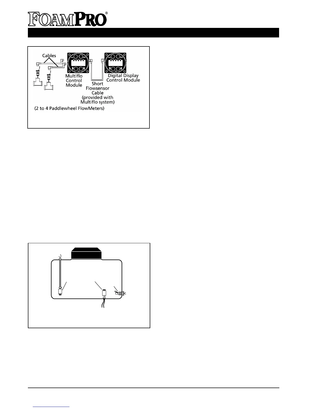
Figure 18. Foam Tank Low Level Sensor
Mounting Options
be hung from a long nipple attached to the top
of the tank. The nipple should be rigid enough
to withstand the force of sloshing foam when the
vehicle is in motion. Make sure the low level
sensor does not contact the side of the foam
tank when the vehicle is in motion (See Figure
18). Since wire connections must be made
inside the nipple, a
3
/8 inch NPT nipple with
3
/8
by
1
/8 inch NPT reducer at the lower end is the
minimum size recommended.
CAUTION: The foam tank low level sensor must
be utilized to protect the foam pump from dry
running. Failure to do so will void the warranty.
Connect the sensor wires to the low tank sensor
cable (blue coded cable ends). The low tank
switch sensor cable may be shortened or
lengthened (use 18-22 AWG). It has pigtails at
one end and is not polarity sensitive. Connect
the other cable end to the motor driver box on
the foam pump/motor base assembly (see
Figure 16).
Check low level sensor operation after
installation using a powered test light. With no
foam in the tank, the light should be on. If this
is not the case, remove the clip from the end of
the sensor. Remove the float and reinstall 180
o
out of position. Reinstall clip.
A side mount low tank sensor is available to be
used if both the top and bottom of the tank is
not accessible (See Figure 18). The side mount
low tank sensor has
1
/2 inch NPT threads and
the center of the switch must be located
approximately 2 inches [51 mm] from the bottom
of the foam tank with the float positioned on top
of the switch to move up and down.
NOTE: When the side mount low tank sensor
senses a low concentrate condition, the
system will operate for two minutes unless
the foam concentrate level is restored. If the
foam concentrate level is not restored, the
system will shut down after two minutes.
When locating the side mount low tank level
switch on the foam tank, sufficient foam
volume must be present for two minutes of
operation. This determination will be made
using the most frequent foam concentrate
injection rate and water flow.
The side mount low tank sensor must be sealed
with a suitable sealant to prevent concentrate
leakage. After installation, check operation of
the side mount low tank sensor with a powered
test light. With no foam in the tank, the light
should be on. If light does not come on, rotate
the side mount low tank sensor until the test
light is on. The float should be allowed to swing
up and down freely.
D. DC MOTOR
Provide adequate electrical power (see the
listing on Page 15) from the battery. Use
8 AWG minimum wire directly to the battery or
battery switch. Long wire runs may require
6 AWG wire for proper operation.
Figure 17. Multiflo and Flowmeter
Connections
Top Mount
Low Tank Sensor
BOTTOM MOUNT
Side Mount
Tank Sensor
(OPTIONAL)