5
Installation and Operation Manual
SystemsSystems
2001 and 2002
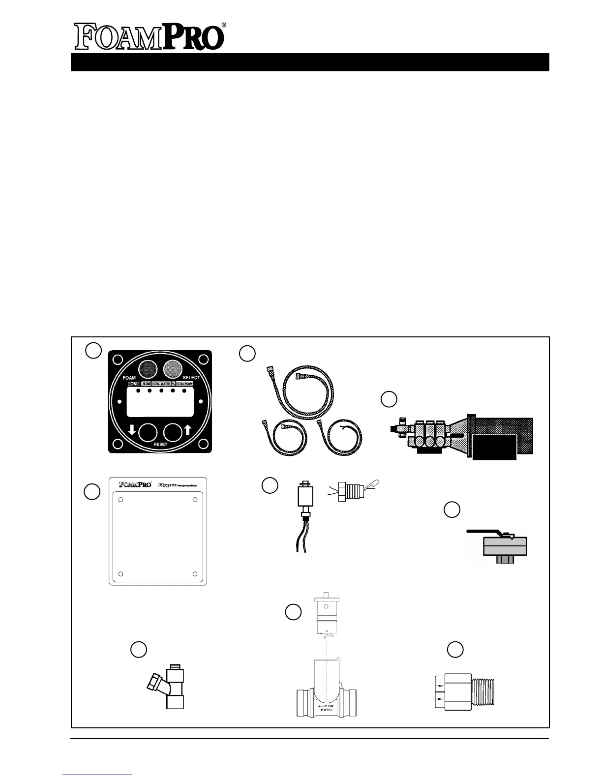
SYSTEM COMPONENT DESCRIPTION
1
2
4
STANDARD FOAMPRO 2001 and 2002 EQUIPMENT
The following components are packaged with the
FoamPro 2001 and 2002
1. DIGITAL DISPLAY CONTROL MODULE
2. MOLDED CABLES
3. FOAM PUMP ASSEMBLY
4. INSTRUCTION PLATE
5. TANK LOW LEVEL SENSOR (One
required. Not packaged with the unit.
Order separately.)
6. CALIBRATE/INJECT VALVE with
BUSHING (Attached to the pump outlet
connection.)
7. INLET LINE STRAINER WITH NIPPLE
8. FOAMPRO PADDLEWHEEL FLOWMETER
(The flowmeter is a required component and
must be ordered separately. When ordering the
2001 or 2002, specify the flowmeter size based
on end use requirements. The flowmeters are
available with 1-1/2 NPT x 1" Bore, 1-1/2, 2,
2-1/2, 3 and 4 inch NPT threads. (Part numbers
and flow ranges for the various flowmeters can
be found on Page 41.)
9. 1/2 INCH NPT FOAM INJECTION CHECK
VALVE. This NFPA 1906 required check valve
prevents water back flowing into foam systems.
6
3
9
5
Vertical Mount
(P/N 2510-0028)
Side Mount
(P/N 2510-0032)
7
3
To Operator:
1. Push red foam button. Light below switch
will indicate unit is operating and will flash
when foam is being injected.
2. Change foam percentage using
keys.
3. Gray select button will display
water flow, total water flowed,
foam concentration and total foam
flowed. Push keys together to
reset total values.
4. To shut down, depress the red foam
button.
➞
➞
➞
➞
Read and Understand
Operating Manual
800-533-9511
HYPRO
8