38
Installation and Operation Manual
SystemsSystems
2001 and 2002
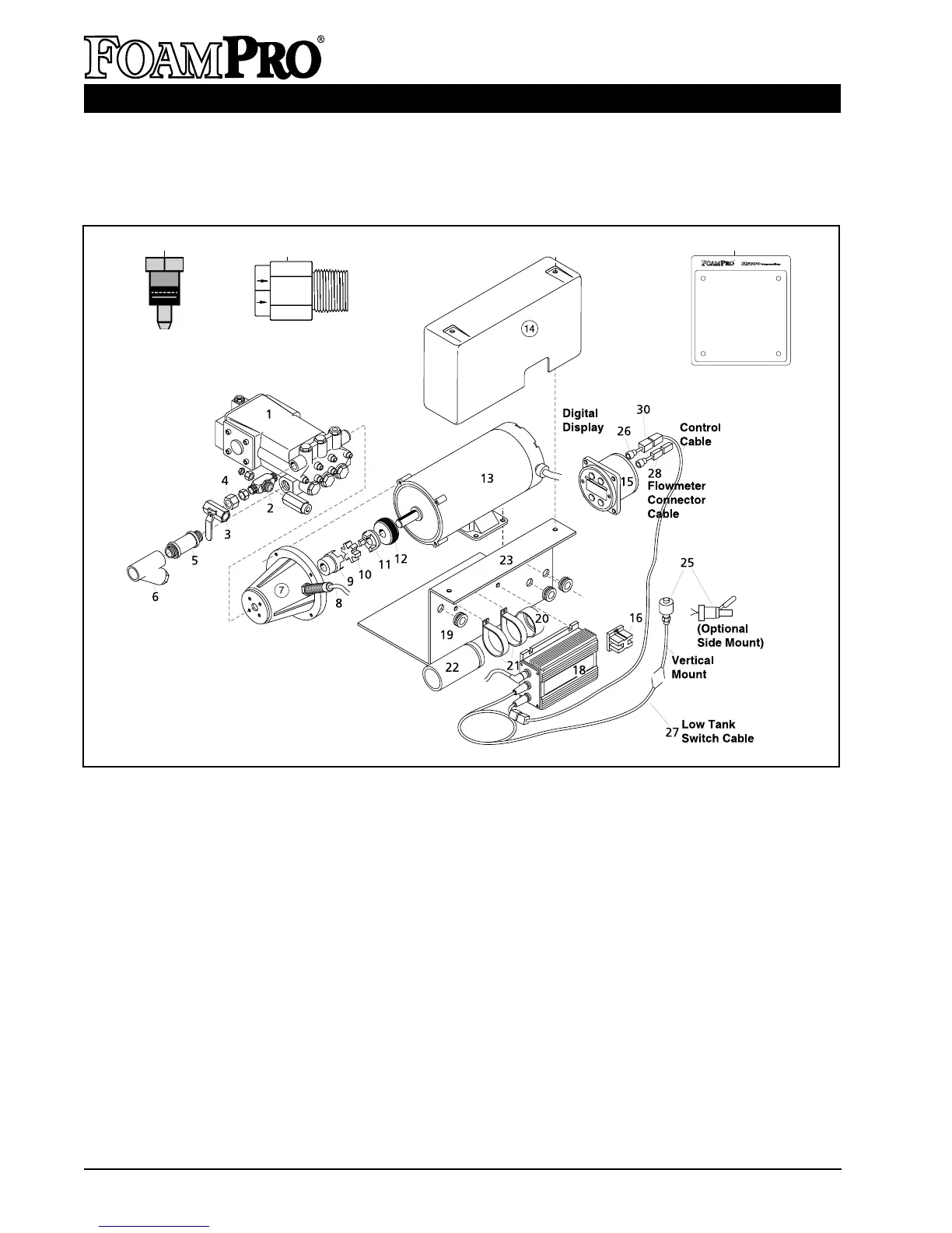
PARTS IDENTIFICATION FOR SYSTEM 2001
Ref. Part No. Description Qty.
1 2341B-P-01 Foam Pump Assembly-2001 1
2 3300-0092 Relief Valve 1
3 3304-0025 Cal/Inject Valve 1
4 2404-0271 Reducer 1
5 2401-0038
1
/2 inch NPT Tee 1
6 3350-0135 Line Strainer (
3
/4 inch NPT) 1
7 0704-8600A1 Flange Adaptor 1
8 2530-0064 Speed Sensor 1
9 2738-2003 Coupling Body
3
/4 inch [19 mm] 1
10 2728-0001 Rubber Disc 1
11 2738-2002 Coupling Body
5
/8 inch [16 mm] 1
12 3115-0029 Gear 1
13 2570-0011 Electric Motor (1/2 hp; 12 V) 1
13 2570-0020 Electric Motor (1/2 hp; 24 V) 1
14 2840-0071 Shield 1
15 2527-0067 Digital Display Control 1
16 2530-0096 Terminal Block 1
18 2527-0071 Motor Driver Box 1
Ref. Part No. Description Qty.
19 1700-0120 Grommet 1
20 1450-0010 Plastic Cap 1
21 2910-0011 Clamp, Vinyl Coated 2
22 2530-0061 Capacitor (82,000uF) 1
23 1510-0086 Mounting Bracket 1
24 2404-0182 Injector Fitting 1
25 2510-0028 Tank Level Sensor (Vertical) 1
2510-0032 Tank Level Sensor (Side) 1
26 2520-0048 Control Cable (6 ft. [2 m] Lg) 1
2520-0049 Control Cable (12 ft. [3 m] Lg) (Std)1
2520-0050 Control Cable (20 ft. [5 m] Lg) 1
27 2520-0042 Tank Sensor Cable 1
28 2520-0045 Flowmeter Cable (6 ft. [2 m] Lg) 1
2520-0046 Flowmeter Cable (12 ft. [3 m] Lg) (Std)1
2520-0047 Flowmeter Cable (20 ft. [5 m] Lg) 1
30 3430-0351 RFI Kit for Controller (4 pcs) 1
3430-0353 RFI Kit for Flowmeter (4 pcs) 1
31 6032-0012 Placard
32 3320-0027 Check Valve,
1
/2 inch 1
13
¤
To Operator:
1. Push red foam button. Light below switch
will indicate unit is operating and will flash
when foam is being injected.
2. Change foam percentage using
keys.
3. Gray select button will display
water flow, total water flowed,
foam concentration and total foam
flowed. Push keys together to
reset total values.
4. To shut down, depress the red foam
button.
➞
➞
➞
➞
Read and Understand
Operating Manual
800-533-9511
24
32
31