41
Installation and Operation Manual
SystemsSystems
2001 and 2002
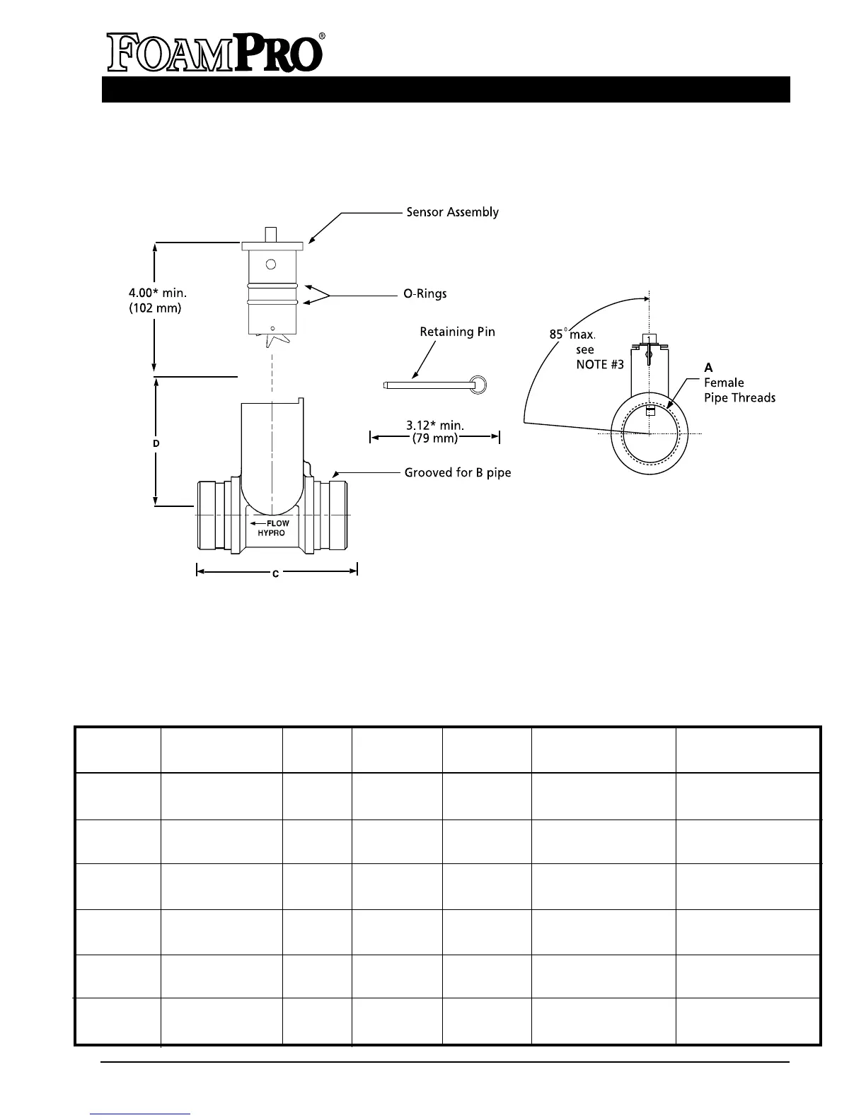
Assy. Part A B C D Maximum Accuracy Maximum Operating
Number Flow Range (gpm) Flow Range (gpm)
2660-0030 1-1/2''—11-1/2'' NPT 2'' Pipe 7-3/8'' [188 mm] 3-7/8'' [99 mm] 5-110 3-145
NOTE 1'' I.D. Bore
2660-0031 1-1/2"—11-1/2" NPT 2" Pipe 5-3/8" [137 mm] 4-1/8" [105 mm] 10-320 3-380
2660-0031B 1-1/2"—11" BSP 2" Pipe 5-3/8" [137 mm] 4-1/8" [105 mm] 10-320 3-380
2660-0032 2"—11-1/2" NPT 2-1/2" Pipe 5-3/8" [137 mm] 4-3/8" [111 mm] 15-520 5-625
2660-0032 2"—11" BSP 2-1/2" Pipe 5-3/8" [137 mm] 4-3/8" [111 mm] 15-520 5-625
2660-0033 2-1/2"—8" NPT 3" Pipe 5-3/8" [137 mm] 4-9/16 [116 mm] 20-750 8-900
2600-0033B 2-1/2"-11" BSP 3" Pipe 5-3/8" [137 mm] 4-9/16 [116 mm] 20-750 8-900
2660-0034 3"—8" NPT 4" Pipe 5-1/2" [140 mm] 4-7/8 [124 mm] 30-1150 12-1380
2600-0034B 3"—11" BSP 4" Pipe 5-1/2" [140 mm] 4-7/8 [124 mm] 30-1150 12-1380
2600-0035 4"—8" NPT 5" Pipe 5-1/2" [140 mm] 5-3/8" [137mm] 55-1980 20-2380
2660-0035B 4"—11" BSP 5" Pipe 5-1/2" [140 mm] 5-3/8" [137mm] 55-1980 20-2380
NOTES: 1. Use CAUTION not to damage
sensor during assembly.
2. Use Loctite PST 565 or
equivalent Teflon tape to seal
pipe threads.
3. Maximum horizontal installation
angle to allow proper water
drainage. Unit may also be
installed in vertical piping
arrangement.
* = Minimum sensor service clearance.
FoamPro Flowmeter