Description of the menu | 49
FRAKO | Operating Manual | Power Quality Controller – PQC
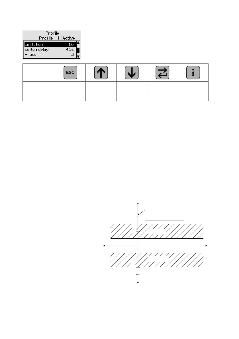
Parametrizing control profile
Key
Action
Profile selec-
tion (Save
Yes/No)
Increase
value +
Decrease
value -
Back to
parameter
selection
–
cos φ
target
0.90 capacitive to 0.80 inductive (in increments of 0.01)
Parallel shift –2.0 to +4.0 (in increments of 0.5)
Limitation –2.0 to +2.0 (in increments of 0.5), OFF or with the SP (parallel
shift) option (mirror image of the characteristic curve across
the y-axis into the regeneration quadrants). Additional informa-
tion is given in the “PQC Application Note”.
Switching delay 5 to 500 seconds (in 1 s increments)
Phase L1, L2 or L3: select control phase
Active Activate control profile (only one profile can be active)
Setting cosφ
target
The desired value of cosφ
target
can be set from 0.80 inductive to 0.90 capacitive in
increments of 0.01. The mode of operation of this adjustment can be seen in the
following diagrams:
Control characteristic at
cosφ
target
=1
Limitation=0
Parallel shift=0
If the system operates within the
band range shown, no switching
operations will be activated.
Active power
Reactive power
ind
2
3
cap
Regeneration
Switch in
Switch out
One division =
0.65 × smallest cap.
stage
-3
-2