Description of the menu | 51
FRAKO | Operating Manual | Power Quality Controller – PQC
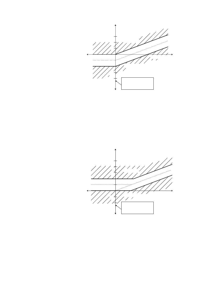
Control characteristic at
cosφ
target
=0.92 ind
Limitation = OFF
Parallel shift = –1.0 (capacitive)
Here the set cosφ
target
constitutes
the lower (more inductive) limit of
the control band. When regenera-
tion occurs, the lower (more induc-
tive) limit constitutes a cos φ
target
of 1. This means that no inductive
reactive power can result during
feed-in operation.
Limitation
This setting gives new possibilities that could not be attained previously due to con-
flicting requirements.
The range of values for limitation are -2 to +2 in increments of 0.5, plus the setting
OFF. Setting the limitation at 1 and cosφ
target
at 1.00 has exactly the same effect as the
parallel shift described above. If cosφ
target
is not set at 1, a kink results in the control
curve, as shown in the following example. The limitation forms an absolute boundary
beyond which the reactive power may not go.
Control characteristic at
cosφ
soll
=0.92 ind
Limitation=+1.0
Parallel shift= 0.0
This setting has the following
effects:
– The set cosφ
target
is attained,
on average, in the upper power
range.
– Overcorrection (capacitive,
usually disruptive) is avoided in
the low load range.
Reactive power
ind
4
3
cap
Regeneration
Switch in
Switch out
One division =
0.65 × smallest cap.
stage
-2
-1
Active power
Reactive power
ind
2
1
cap
Regeneration
Switch in
Switch out
One division =
0.65 × smallest cap.
stage
-3
Reactive power
ind
4
3
cap
Regeneration
Switch in
Switch out
One division =
0.65 × smallest cap.
stage
-2
-1
Active power
Reactive power
ind
2
1
cap
Regeneration
Switch in
Switch out
One division =
0.65 × smallest cap.
stage
-3
Active power