ELA100 Rev0604
18
Notes:
- Not all wires are used for all engines.
- For Ford 6.0L engines the yellow RPM signal wire, pin 12, should be connected
to the Clean Tachometer Output [green/white wire, circuit #76].
WIRING
The following figures include the schematics, wiring diagrams, block diagrams,
and cables for the ThrottleXcel.
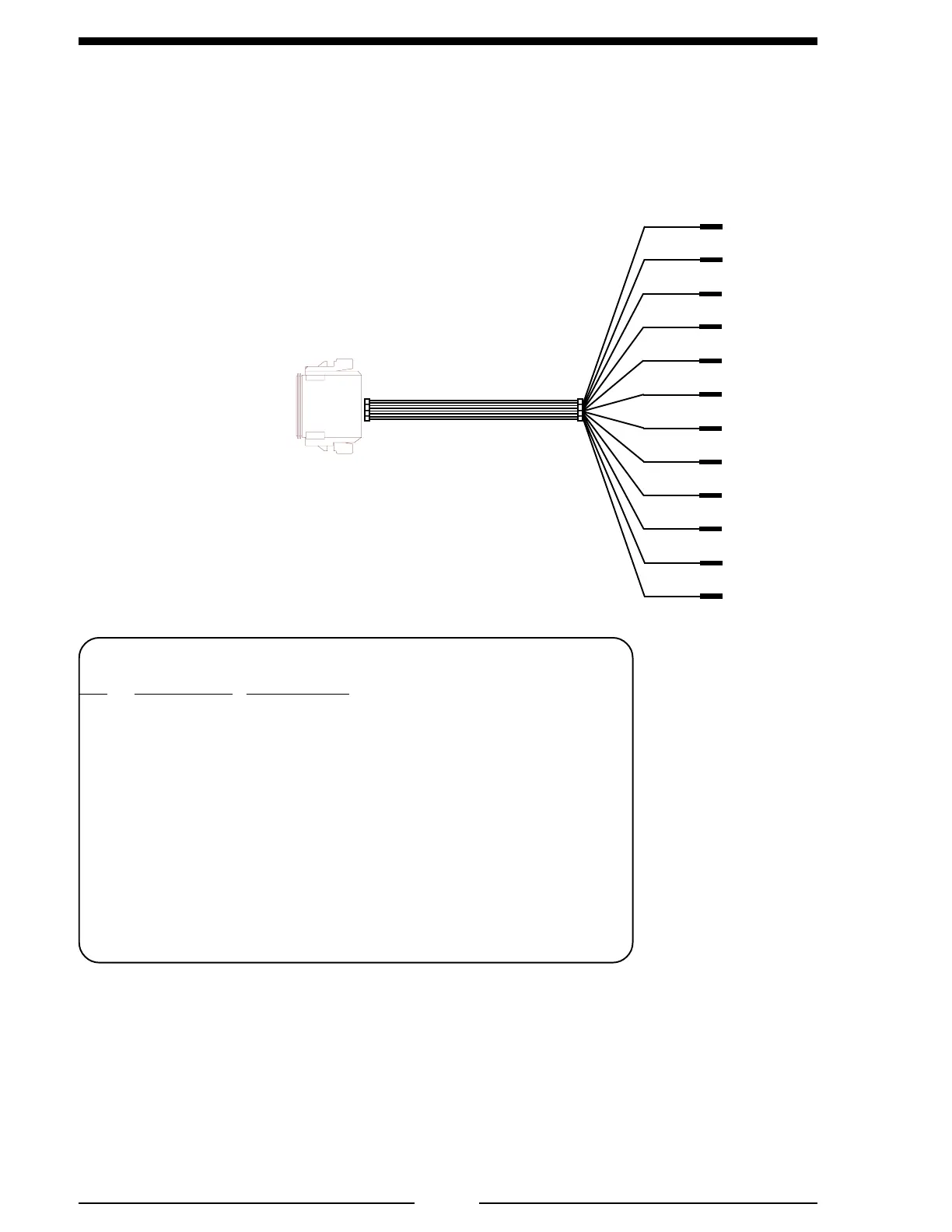
Connectors and Cables
Figure 3. 12-Pin Connector Wiring
12-Pin
Deutsch
Connector
Butt
Connectors
12 Pin Connector/Cable
Pin Wire Color Description
1NC -
2NC -
3NC -
4 BLU Engine Oil Press. Sensor Signal
5 ORG Engine Temp. Sensor Signal
6 BRN Buzzer Ground (300mA)
7 VIO High Idle Active Input (+12 VDC)
8 WHT High Idle Throttle Enable Input (+12 VDC)
9 BLK CAN J1939 (–)
10 RED CAN J1939 (+)
11 GRN Transmission Temp. Sensor Signal
12 YEL RPM Signal
NC
NC
NC
BLU
ORG
BRN
VIO
WHT
BLK
RED
GRN
YEL
12-Pin Cable

 Loading...
