ELA100 Rev0604
32
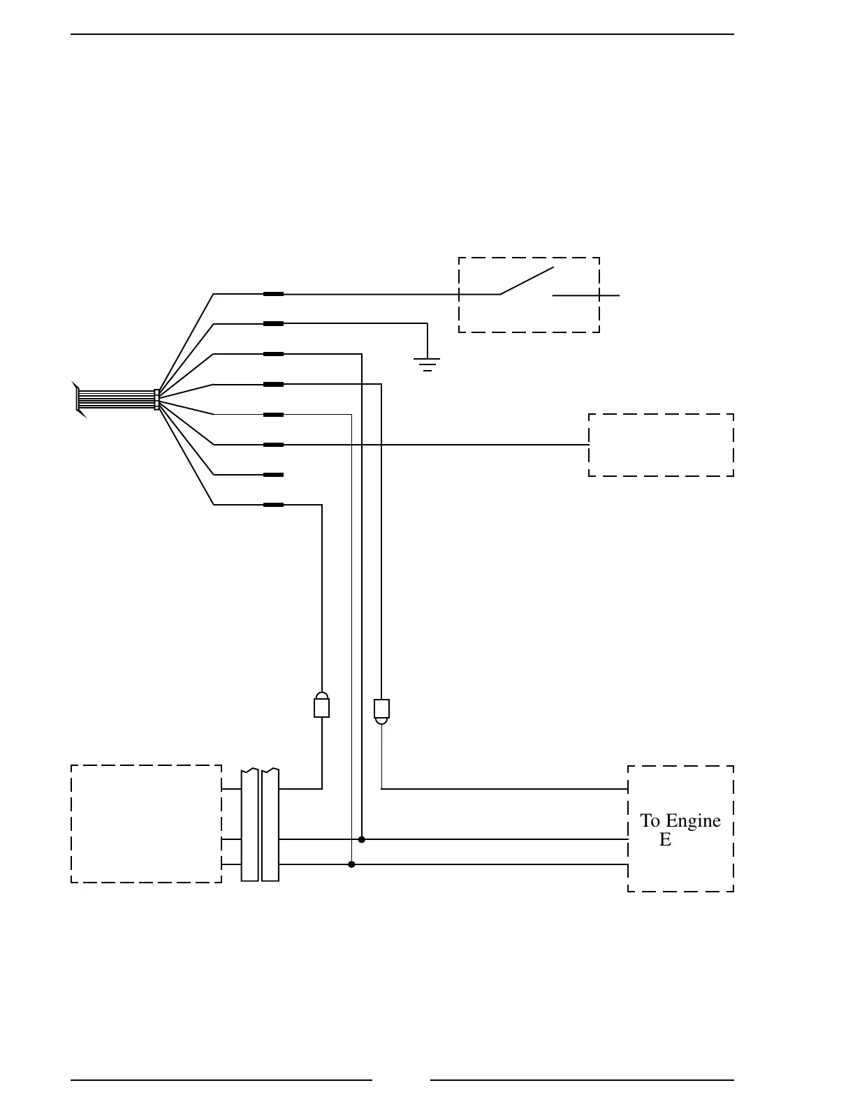
Mack Harness Connections
Interface Information
The 8-Pin cable needs to be wired to the cab foot throttle harness. Use a voltmeter
to determine which pins are 5 V Reference and Engine Control Signal.
Engine Control Signal will be 0.7 volts at idle and rise to approximately 3.8
volts as the foot pedal is pressed.
Cab Foot
Throttle
Cab Foot
Throttle
Connector
+12 (24)
VDC
Ignition Key
GND
+12 (24) VDC
Pump Engaged
Interlock
8-Pin Cable
(Refer to
Figure 3 )
RED
BLK
ORG
WHT
GRN
YEL
BLU
BRN
To Engine
ECM
Engine Control Signal
(0.7 to 3.8 volts)
Signal Return
5 V Reference
Note: Use a plug and receptacle on the
Engine Control Signal wire so the ends
can be reconnected if the Throttlexcel is
removed.
Figure 11. Mack ELA107 Wiring

 Loading...
