ELA100 Rev0604
19
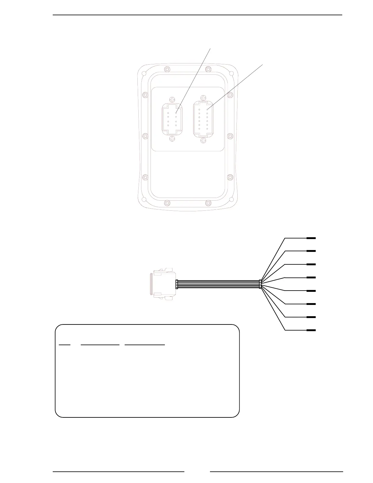
Figure 4. 8-Pin Connector Wiring
8 Pin Connector/Cable
Pin Wire Color Description
1 Red Supply Voltage (9 to 30 VDC)
2 Black Ground
3 Orange +5 VDC Reference From ECM
4 White Throttle Signal To ECM
5 Green Signal Return From ECM
6 Yellow Interlock Input (12 or 24 VDC)
7 Blue Throttle Enable Signal Output
8 Brown Foot Pedal Signal Input
8-Pin
Deutsch
Connector
Note: Not all wires are used for all engines. Refer to the
engine specific wiring diagram for interface connections.
Butt
Connectors
Note: An adapter and cable assembly replaces the basic 8-pin
cable when connecting the ThrottleXcel to a Ford 6.0 or
GMAC engine. Refer to the engine specific wiring diagram.
Control
Module Rear
View
8-Pin
Connector
Pin 1
12-Pin
Connector
Pin 1
8-Pin Cable
RED
BLK
ORG
WHT
GRN
YEL
BLU
BRN

 Loading...
