ELA100 Rev0604
35
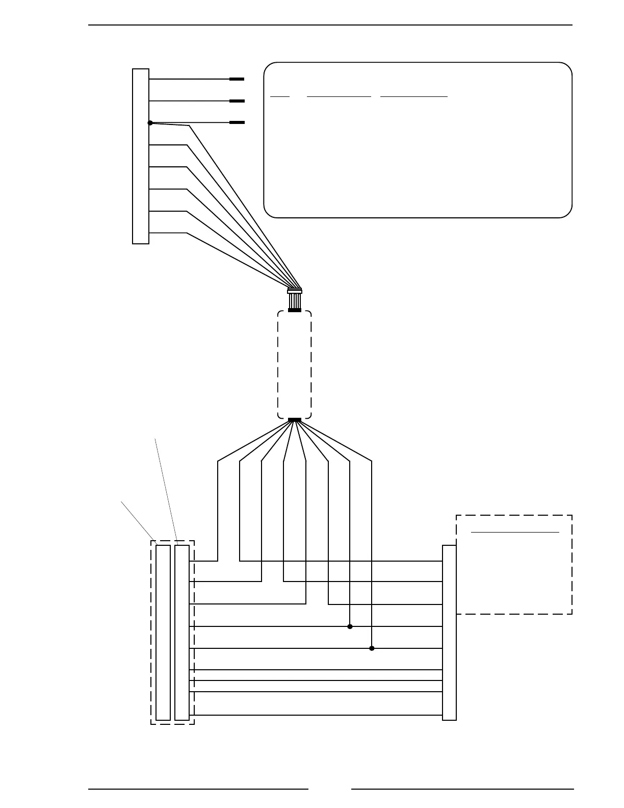
Figure 13. GMAC ELA109 Wiring
(Sheet 2 of 2)
Note: An adapter and cable assembly
replaces the basic cable when
connecting the ELA109 to a GMAC
engine.
Adapter
Assembly
10 Pin
Matripack
Plug
10 Pin
Matripack
Receptacle
Adapter Connector/Cable
Pin Wire Color Description
1 Red Supply Voltage (12 or 24 VDC)
2 Black Ground
3 Blue +5 VDC Reference From ECM
4 White Throttle Signal To ECM
5 Brown Signal Return From ECM
6 Yellow Interlock Input (12 or 24 VDC)
7 Green Throttle Enable Signal
8 Black Foot Pedal Signal Input
To Cab
Foot
Throttle
Connector
To Engine
ECM
Harness
Connector
2002 and
Earlier
Model
Engines
2003
Model
Engines
RPM Signal Levels
@IDLE@MAX
4.4V 2.3V
0.65V 2.7V
4.0V 2.8V
+5 VDC
Ground
H
E
A
K
J
B
D
G
C
F
C
F
K
A
D
B
E
G
H
J
Signal # 2
RED
BLU
WHT
BLK
GRN
BRN
YEL
ORG
Signal # 1
Signal # 3
YEL
BLK
RED
BLU
WHT
BRN
GRN
BLK
6
2
1
3
4
5
7
8
GMAC Adapter and Cable Detail
Do not mount in the
engine compartment

 Loading...
