Installation
16
INSTALLATION
We recommend that an authorized Heart Interface technical
dealer or experienced electrician install your Freedom In-
verter/Charger.
Consult the NEC and your local electrical codes for electrical
wiring specifications.
Confirm that your shipping carton contains:
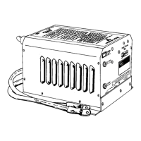
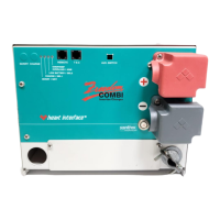
• Inverter/charger
• Owners manual (this manual)
• Warranty card
• TSC temperature sensor with 15’ cable
• Wire nuts
• Two battery terminal covers, one red and one black
Before You Install Your Freedom Inverter/Charger
Gather the following supplies:
• Fuse—UL Listed, DC Rated slow blow class “T” fuse as
required by NEC. See “Recommended Fuses” chart on
page 27.
• 10-gauge electrical wire for AC input wiring.
• Electrical wire for AC output wiring. Select the correct
gauge for your Freedom Inverter/Charger model, and
type of installation. Consult the NEC for further informa-
tion.
• Battery Cables: one negative (-) cable, one short positive
(+) cable (maximum 18”) and one longer positive (+) cable.
Consult NEC for proper cable size. See “Selecting Battery
Cables” on page 24.
• Four mounting screws or 1/4” bolts.
 Loading...