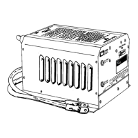
Installation
22
• If your unit has dual AC outputs, and you are using
both AC outputs, feed two AC output wire(s) through
the strain relief and into the AC wiring compartment.
4. Strip 1/2 inch of insulation off each conductor.
5. Connect each wire to the unit’s AC output wires:
• Black to black (hot or line)
• White to white (neutral)
• Green or bare copper to AC GROUND STRIP (ground)
Use the provided wire nuts to make the wire connections.
You may also use butt splices (not included) to make the
wire connections.
6. Tug firmly on each connection to make sure they are
secure. Later, if the unit is not operating properly, check
these connections first.
7. Carefully tuck all the wires into the AC wiring compart-
ment.
8. Replace the cover plate.
Connect the grounding wires
For safety purposes, the chassis of the inverter/charger must
be connected to your AC ground system.
Check the NEC and your local electrical codes for further
information on grounding.
Note: Do not connect the battery cables to the AC ground strip
or to the chassis ground lug of the unit.
To ground a unit using the ground lug
1. Use 8 AWG bare copper or green insulated wire.
Note: Some installations require a heavier grounding wire.
Check the NEC and your local electrical codes for specifi-
cations.
2. If you are using green, insulated wire, strip both ends of
the wire.
3. Secure the wire to the chassis ground lug using the 3/16”
Allen wrench.
Ground Lug
 Loading...