Figure 25
-ULTIPLESEPARATEPIPESSIDEWALLTERMINATIONS
MAINTAINVERTICALSPACINGBETWEENVENTANDAIR
lTTINGSSHOWNIN&IGUREPAGE.
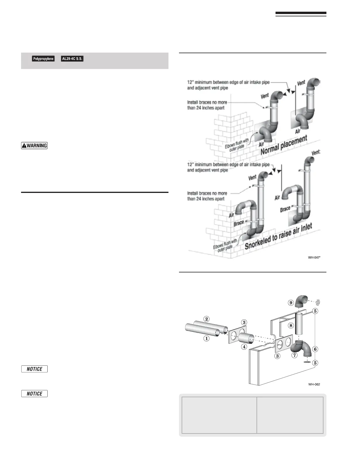
Figure 26 3IDEWALLTERMINATIONASSEMBLYUSING
SEPARATEPIPES
See notices on previous page.
Part number 550-142-850/0716
24
FreeStyle
®
WALL MOUNT GAS-FIRED WATER BOILER — Boiler Manual
10 DIRECT VENT — Sidewall with separate pipes continued
a. #UTAHOLEFORTHEVENTPIPE&OREITHERCOMBUSTIBLEOR
noncombustible construction, size the vent pipe hole at
least 0.4” larger than the vent pipe diameter.
b. Insert a galvanized metal thimble in the vent pipe hole
as shown in Figure 26.
c. 0LATEMAY BElELDFABRICATEDFROMCORROSIONRESISTANT
MATERIALOFSUFlCIENTSTRENGTH0LATEMUSTALLOWVENTING
to maintain minimum clearance to combustibles.
Ensure that the plate material is strong enough to
PREVENTTHETERMINATIONFROMBEINGPUSHEDINWARD
IFSTRUCKORPUSHEDFROMTHEOUTSIDE
1. &OLLOWALLLOCALCODESFORISOLATIONOFVENTPIPEWHENPASSING
through floors or walls.
2. Seal exterior openings thoroughly with exterior caulk.
Termination and fittings
1. Prepare the vent termination elbow and the air ter-
mination elbow by inserting bird screens.
(See Figure 24, page 23.) Bird screens must be purchased
SEPARATELY3EE THE PARTSLIST AT THE END OFTHISMANUALFOR
part numbers.
2. Secure the elbows so they will butt against the sidewall ter-
mination plate.
3. When completed, the air termination coupling must be
oriented at least 12 inches below the vent termination and
at least 12 inches above grade or snow line as shown in Fig-
ure 24, page 23.
+EEPVENTSAIRINTAKEAREACLEAROFACCUMULATING
snow.
4. You can orient the vent termination elbow either directly
OUTWARDORDEGREESAWAYFROMTHEAIRINLETELBOWASSHOWN
in Figure 24, page 23.
5. -AINTAINTHEREQUIREDDIMENSIONSOFTHElNISHEDTERMINATION
piping as shown in Figure 24, page 23.
6. For multiple boiler terminations, see Figure 25.
7. $ONOTEXTENDEXPOSEDVENTPIPEOUTSIDEOFBUILDINGMORE
THANSHOWNINTHISDOCUMENT#ONDENSATECOULDFREEZEAND
block vent pipe.
)FEXTENDINGTHEVENTANDAIRPIPESOUTFROMTHEWALL
INSTALLACOUPLINGONEACHPIPE-OUNTTHEPIPING
with the coupling flush with the outer plate.
Wall penetration thickness between 2” to 24”.
1 Vent piping
2 Air piping
3 Sidewall termination plates: for 3” PVC
or 3” AL29-4C or 2” PVC, (field supplied)
4 Galvanized thimbles, by installer
5 Bird screen, by installer
6 Air inlet elbow
7 Elbow
8 Nipple
9 Vent termination elbow