Part number 550-142-850/0716
25
FreeStyle
®
WALL MOUNT GAS-FIRED WATER BOILER — Boiler Manual
11 DIRECT VENT — Sidewall concentric
Allowable vent/air pipe materials
& lengths
1. The concentric termination kit must be purchased
separately.
Use only the vent materials and kits listed in
Figure 21, page 19
0ROVIDEPIPEADAPTERSIF
specified.
2. Locate the termination such that the total air pip-
INGANDVENTPIPINGFROMTHEBOILERTOTHETERMINA-
tion will not exceed the maximum length given in
Figure 20, page 18
.
3. This termination requires a 45-degree elbow that is
not supplied with the termination kit. The maximum
VENTAIRPIPELENGTHSINCLUDEALLOWANCEFORTHISELBOW
For polypropylene applications, comply
with any additional requirements in the
VENTSYSTEMMANUFACTURERSINSTRUCTIONS
(Do Not use 3” PVC transition pieces at the
boiler vent and air connections)
and at the
TERMINATIONIFUSING A v 06# CONCENTRIC
vent kit. Install a locking collar at every joint.
&OR!,#VENTPIPEAPPLICATIONSCOMPLY
with any additional requirements in the vent
SYSTEMMANUFACTURERSINSTRUCTIONS
Provide
A!,#STARTERPIECEFROMTHE!,#
MANUFACTURERTOTHE
transition at the boiler
VENTCONNECTION!IRPIPEMUSTBE06#OR
CPVC. Provide a 3” PVC transition at the
BOILERAIR CONNECTIONIFUSING v AIR PIPE
Provide transition pieces to PVC at the vent
and air pipe termination connections.
Wall penetration thickness between 2” to
24”.
$ETERMINETERMINATIONLOCATION
1. The concentric termination kit must be installed as
shown in Figure 29, page 26.
2. The termination must comply with clearances and
limitations shown in
Figure 22, page 21
.
3. Locate the termination so it is not likely to be damaged
BYFOREIGNOBJECTSSUCHASSTONESORBALLSORSUBJECT
TOBUILDUPOFLEAVESORSEDIMENT
-ULTIPLEVENTAIRTERMINATIONS
1. When terminating multiple boilers, install each con-
centric termination as described in this manual.
!LLVENTPIPESANDAIRINLETSMUSTTERMINATE
ATTHE SAME HEIGHT TOAVOIDPOSSIBILITY OF
severe personal injury, death or substantial
property damage.
2. Place wall penetrations to obtain minimum clearance
as shown in Figure 28, page 26FOR53INSTALLATIONS
3. 4HEAIRINLETOFA&REE3TYLE®BOILERISPARTOFADIRECT
VENTCONNECTION)TISNOTCLASSIlEDASAFORCEDAIRIN-
TAKEWITHREGARDTOSPACINGFROMADJACENTBOILERVENTS
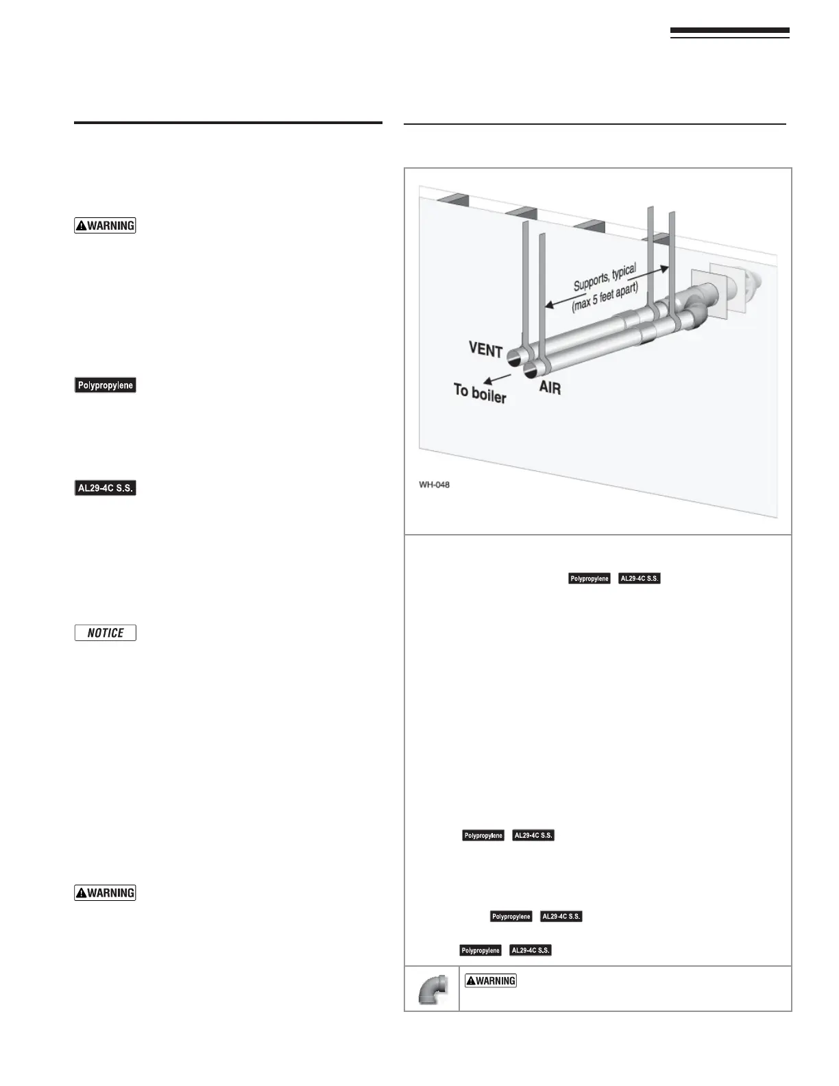
&IGURE ).34!,,!4)/.3%15%.#%#ONCENTRICHORIZONTAL
3TEP 2EADANDFOLLOWALLINSTRUCTIONSINTHISMANUAL$/./4PROCEED
WITH VENTAIR INSTALLATION UNTIL YOU HAVE READ PAGE
THROUGHPAGE
3EENOTICESATLEFT
3TEP )NSTALLTHEBOILERINALOCATIONTHATALLOWSPROPERROUTINGOFALLVENT
and air piping to the selected sidewall location.
3TEP -AKESURETHESELECTEDSIDEWALLTERMINATIONLOCATIONCOMPLIESWITH
Figure 22, page 21-ULTIPLEBOILERCONCENTRICTERMINATIONSMUST
also comply with
Figure 28, page 26
.)
3TEP Use only the vent materials listed in Figure 21, page 19. Provide pipe
adapters where required.
3TEP Vent piping and air piping lengths must not exceed the values shown
in Figure 20, page 18.
3TEP 4HECONCENTRICTERMINATIONMUSTBEASSEMBLEDANDINSTALLEDBEFORE
PIPINGFROMTHEBOILERTOTHETERMINATION
3TEP Prepare the sidewall penetration — assemble the concentric ter-
mination kit and secure the cover plates as instructed in this sec-
tion. Provide the supports indicated and mount the termination
assembly. See “Install termination — concentric pipes” on page 26.
3EENOTICESATLEFT
3TEP Install vent and air piping between the boiler and the concentric
vent/air termination. Slope horizontal piping downward toward the
BOILERATLEASTINCHPERFOOT3EE page 32FORGENERALGUIDELINES
3TEP )NSTALLPIPESUPPORTSEVERYFEETONBOTHTHEHORIZONTALANDVERTICAL
runs.
3EENOTICESATLEFT
3TEP )NSTALLAHANGERSUPPORTWITHININCHESOFANYUPTURNINTHEPIPING
3EENOTICESATLEFT
53%37%%0%,"/73&/2!,,6%.4!.$!)2
0)0).'$/./4USESHORTRADIUSELBOWSFORVENTOR
AIRPIPING"OILERPERFORMANCECOULDBEAFFECTED