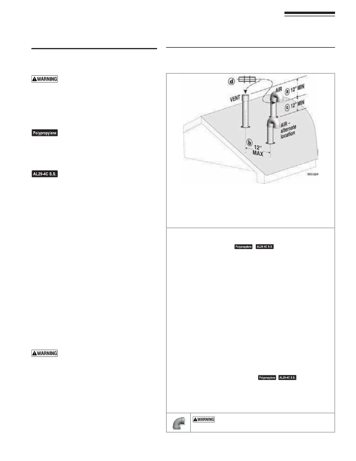
Figure 30 3EPARATEPIPESVERTICALTERMINATION
4ERMINATEVENTANDAIRPIPESSUCHTHAT
A !)2).4!+%)3!4,%!34INCHESBELOWVENTOUTLET
B !)2).4!+%IS NO FURTHER than 12 inches away center to center
C !)2 ).4!+% )3 !4 ,%!34 INCHESABOVEROOF OR SNOW LINE
KEEPVENTSAIRINTAKEAREACLEAROFACCUMULATINGSNOW
D 6ENTANDAIRTERMINATIONSARElTTEDWITHBIRDSCREENS
3TEP 2EADANDFOLLOWALLINSTRUCTIONSINTHISMANUAL$/./4PROCEED
WITH VENTAIR INSTALLATION UNTIL YOU HAVE READ PAGE
THROUGHPAGE
3EENOTICESATLEFT
3TEP )NSTALLTHEBOILERINALOCATIONTHATALLOWSPROPERROUTINGOFALLVENT
and air piping to the selected sidewall location.
3TEP -AKESURETHE SELECTEDVERTICAL TERMINATION LOCATION COMPLIESWITH
&IGUREPAGE-ULTIPLEBOILERTERMINATIONSMUSTALSOCOMPLY
with Figure 31, page 28.)
3TEP Use only the vent materials listed in Figure 21, page 19. Provide pipe
adapters where required. Vent piping and air piping lengths must not
exceed the values shown in Figure 20, page 18.
3TEP Prepare the vertical penetrations and secure penetration components as
INSTRUCTEDINTHISSECTION3EEh0REPAREROOFPENETRATIONSvON page 28
and “Termination and fittings” on page 28.
3TEP The air piping must terminate in a 180-degree return bend or down-
turned elbow as shown above. The vent piping must terminate in a
COUPLINGPOINTEDUPWARD as shown above.
3TEP Install vent and air piping between the boiler and the vertical termina-
tions. Slope horizontal piping downward toward the boiler at least 1/4
INCHPERFOOT)NSTALLPIPESUPPORTSEVERYFEETONBOTHTHEHORIZONTAL
ANDVERTICALRUNS)NSTALLAHANGERSUPPORTWITHININCHESOFANYUPTURN
in the piping. See page 32FORGENERALGUIDELINES!LSOCOMPLYWITHVENT
PIPEMANUFACTURERSINSTRUCTIONS
3EENOTICESATLEFT
3TEP Insert the vent and air piping through the vertical penetrations and
secure the termination fittings.
3TEP -AINTAINCLEARANCESSHOWNABOVE6ENTANDAIRTERMINATIONSMUSTBE
fitted with a bird screen as shown.
53% 37%%0 %,"/73 &/2 !,,6%.4 !.$ !)2
0)0).'$/./4USESHORTRADIUSELBOWSFORVENTOR
AIRPIPING"OILERPERFORMANCECOULDBEAFFECTED
Part number 550-142-850/0716
27
FreeStyle
®
WALL MOUNT GAS-FIRED WATER BOILER — Boiler Manual
Allowable vent/air pipe materials
& lengths
Use only the vent materials and kits listed
in Figure 21, page 19. Provide pipe adapt-
ERSIFSPECIlED
1. Locate the terminations such that the total air piping
ANDVENTPIPINGFROMTHEBOILERTOTHETERMINATION
will not exceed the maximum length given in Fig-
ure 19, page 19.
For polypropylene applications, comply
with any additional requirements in the
VENTSYSTEMMANUFACTURERSINSTRUCTIONS
(Do Not use 3” PVC transition pieces
at the boiler vent and air connections).
Install a locking collar at every joint.
&OR!,# VENTPIPE APPLICATIONS
comply with any additional requirements
INTHEVENTSYSTEMMANUFACTURERSINSTRUC-
tions. 0ROVIDE A!,# STARTER PIECE
FROMTHE!,# MANUFACTURERTOTHE
transition piece at the boiler vent con-
nection. The air piping must be PVC or
CPVC. Provide a 3” PVC transition piece
ATTHEBOILERAIRCONNECTIONIFUSINGvAIR
piping.
$ETERMINETERMINATIONLOCATION
1. The air and vent terminations must be installed as
shown in Figure 30.
2. The terminations must comply with clearances and
limitations shown in Figure 21, page 22.
3. Locate the terminations so they are not likely to be
DAMAGEDBYFOREIGNOBJECTSSUCHASSTONESORBALLS
ORSUBJECTTOBUILDUPOFLEAVESORSEDIMENT
-ULTIPLEVENTAIRTERMINATIONS
1. When terminating multiple boilers, terminate each
vent/air connection as described in this manual.
Terminate all vent pipes at the same height
and all air pipes at the same height to
AVOIDPOSSIBILITYOFSEVEREPERSONALINJURY
death or substantial property damage.
2. 0LACEROOFPENETRATIONSTOOBTAINMINIMUMCLEAR-
ANCEOFINCHESBETWEENEDGEOFAIRINTAKEELBOW
ANDADJACENTVENTPIPEOFANOTHERBOILERFOR53
installations (see Figure 34, page 31).
3. 4HEAIRINLETOFAFreeStyle®BOILERISPARTOFADIRECT
VENTCONNECTION)TISNOTCLASSIlEDASAFORCEDAIR
INTAKEWITHREGARDTOSPACINGFROMADJACENTBOILER
vents.
12 DIRECT VENT — 6ERTICALWITHSEPARATEPIPES