Figure 32 ).34!,,!4)/.3%15%.#%#ONCENTRICVERTICAL
Part number 550-142-850/0716
29
FreeStyle
®
WALL MOUNT GAS-FIRED WATER BOILER — Boiler Manual
Allowable vent/air pipe materials &
lengths
1. The concentric termination kit must be purchased
separately.
Use only the vent materials and kits listed in
Figure 21, page 190ROVIDEPIPEADAPTERSIF
specified.
2. Locate the termination such that the total air piping and
VENTPIPINGFROMTHEBOILERTOTHETERMINATIONWILLNOT
exceed the maximum length given in Figure 20, page 18.
3. This termination requires a 45-degree elbow that is not
supplied with the termination kit. The maximum vent/
AIRPIPELENGTHSINCLUDEALLOWANCEFORTHISELBOW
For polypropylene applications, comply
with any additional requirements in the vent
SYSTEMMANUFACTURERSINSTRUCTIONS(Do Not
use 3” PVC transition pieces at the boiler vent
and air connections)ANDATTHETERMINATIONIF
using a 3” PVC concentric vent kit. Install a
locking collar at every joint.
&OR!,#VENTPIPEAPPLICATIONSCOMPLY
with any additional requirements in the vent
SYSTEMMANUFACTURERSINSTRUCTIONSProvide
A!,#STARTERPIECEFROMTHE!,#
MANUFACTURERTOTHE transition at the boiler
VENTCONNECTION!IR PIPE MUST BE06#OR
CPVC. Provide a 3” PVC transition at the
BOILERAIR CONNECTIONIFUSING v AIR PIPE
Provide transition pieces to PVC at the vent
and air pipe termination connections.
$ETERMINETERMINATIONLOCATION
,OCATETHE CONCENTRICVENTAIRTERMINATIONUSINGTHE FOL-
lowing guidelines:
1. The concentric vent/air assembly must terminate as
shown in Figure 34, page 30.
2. The termination must comply with the clearances and
limitations shown in Figure 21, page 22.
3. Locate the termination so it is not likely to be damaged
BYFOREIGNOBJECTSSUCHASSTONESORBALLSORSUBJECTTO
BUILDUPOFLEAVESORSEDIMENT
-ULTIPLEVENTAIRTERMINATIONS
1. When terminating multiple boilers, install the con-
centric vent/air termination assemblies as described in
this manual.
!LLVENTOUTLETSMUSTTERMINATEATTHESAME
HEIGHTTOAVOIDPOSSIBILITYOFSEVEREPERSONAL
injury, death or substantial property damage.
2. 0LACEROOFPENETRATIONSTOOBTAINMINIMUMCLEAR-
ANCEOFINCHESBETWEENTHEEDGESOFADJACENT
VENTPIPESOFOTHERBOILERSFOR53INSTALLATIONSSEE
Figure 33, page 30).
3. 4HEAIRINLETOFAFreeStyle®BOILERISPARTOFADIRECT
VENTCONNECTION)TISNOTCLASSIlEDASAFORCEDAIRIN-
TAKEWITHREGARDTOSPACINGFROMADJACENTBOILERVENTS
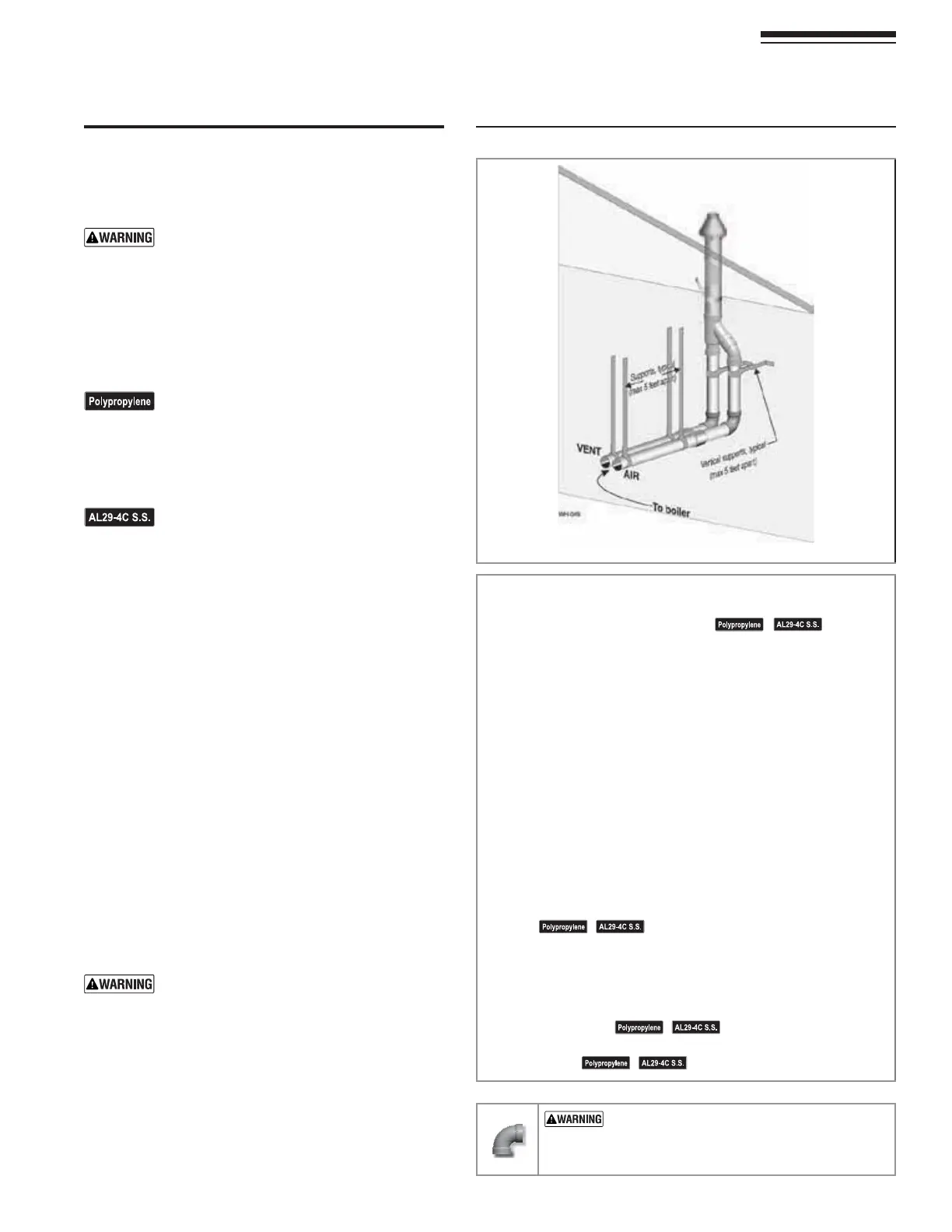
13 DIRECT VENT — 6ERTICALCONCENTRIC
3TEP 2EADANDFOLLOWALL INSTRUCTIONS IN THIS MANUAL$/ ./4
PROCEEDWITHVENTAIRINSTALLATIONUNTILYOUHAVEREAD
PAGETHROUGHPAGE
See notices
ATLEFT
3TEP )NSTALLTHEBOILERINALOCATIONTHATALLOWSPROPERROUTINGOFALL
vent and air piping to the selected sidewall location.
3TEP -AKESURETHESELECTEDVERTICALTERMINATIONLOCATIONCOMPLIES
WITH&IGUREPAGE-ULTIPLEBOILERCONCENTRICTERMINATIONS
must also comply with Figure 33, page 30.)
3TEP Use only the vent materials listed in Figure 21, page 19. Provide
pipe adapters where required.
3TEP Vent piping and air piping lengths must not exceed the values
shown in Figure 20, page 18.
3TEP The concentric termination must be assembled and installed
BEFOREPIPINGFROMTHEBOILERTOTHETERMINATION
3TEP Prepare the vertical penetration(s) — assemble the concentric
termination kit and secure the penetration components as
instructed in this section. Provide the supports indicated and
MOUNTTHETERMINATIONASSEMBLY3EEh0REPAREROOFPENETRATIONSv
on page 30ANDh-OUNTCONCENTRICTERMINATIONvON page 30.
3EENOTICESATLEFT
3TEP Install vent and air piping between the boiler and the concentric
vent/air termination. Slope horizontal piping downward toward
THEBOILER AT LEAST INCHPER FOOT3EE page 32 FOR GENERAL
guidelines.
3TEP )NSTALLPIPESUPPORTS EVERY FEET ONBOTHTHEHORIZONTALAND
vertical runs.
3EENOTICESATLEFT
3TEP )NSTALLAHANGERSUPPORTWITHININCHESOFANYUPTURNINTHE
piping.
3EENOTICESATLEFT
53%37%%0%,"/73 &/2 !,,6%.4!.$
!)2 0)0).' — DO NOT use short radius elbows
FORVENTOR AIRPIPING"OILER PERFORMANCECOULDBE
AFFECTED