Figure 24 ).34!,,!4)/.3%15%.#%3EPARATEPIPES
SIDEWALL
Part number 550-142-850/0716
23
FreeStyle
®
WALL MOUNT GAS-FIRED WATER BOILER — Boiler Manual
10 DIRECT VENT — Sidewall with separate pipes
Allowable vent/air pipe materials &
lengths
Use only the vent materials and kits listed in
Figure 21, page 190ROVIDEPIPEADAPTERSIFSPECIlED
1. Locate the termination such that the total air piping and vent
PIPINGFROMTHEBOILERTOTHETERMINATIONWILLNOTEXCEEDTHE
maximum length given in Figure 20, page 18.
For polypropylene applications, comply with any
ADDITIONALREQUIREMENTSINTHEVENTSYSTEMMANUFAC-
TURERSINSTRUCTIONS$O.OTUSEv06#TRANSITION
pieces at the boiler vent and air connections). Install
a locking collar at every joint.
&OR!,#VENTPIPEAPPLICATIONSCOMPLYWITH
any additional requirements in the vent system
MANUFACTURERS INSTRUCTIONS 0ROVIDE A!,#
STARTERPIECEFROMTHE!,#MANUFACTURERFORTHE
transition piece at the boiler vent connection. The
air piping must be PVC or CPVC. Provide a 3” PVC
TRANSITIONPIECEATTHEBOILERAIRCONNECTIONIFUSING
2” air piping.
$ETERMINETERMINATIONLOCATION
1. Wall penetration thickness between 2” to 24”.
2. The air and vent terminations must be installed as shown in
Figure 24, page 23 and Figure 26, page 24.
3. The terminations must comply with clearances and limitations
shown in Figure 22, page 21.
4. Locate the terminations so they are not likely to be damaged
BYFOREIGNOBJECTSSUCHASSTONESORBALLSORSUBJECTTOBUILDUP
OFLEAVESORSEDIMENT
5. 6ENT ANDAIRLOCATIONSCANBE ON DIFFERENT BUILDING WALLS
Example: Vent/exhaust can be on North building wall and air
INTAKECANBEON3OUTHBUILDINGWALL$IFFERENTPRESSUREZONE
$ONOTEXCEEDTHEMAXIMUMLENGTHSOFTHEOUTSIDE
vent piping shown in Figure 24. Excessive length
EXPOSEDTO THEOUTSIDECOULDCAUSE FREEZINGOF
condensate in the vent pipe, resulting in potential
boiler shutdown. In extremely cold climates, install
an insulated chase around the vent piping, particu-
LARLYIFUSINGLONGERLENGTHS4HECHASEMUSTALLOW
FORINSPECTIONOFTHEVENTPIPEANDINSULATIONMUST
BEPROTECTEDFROMWATER
-ULTIPLEVENTAIRTERMINATIONS
1. When terminating multiple boilers, terminate each vent/air
connection as described in this manual.
2. Place wall penetrations to obtain minimum clearances shown
in Figure 24FOR53INSTALLATIONS
3. 4HEAIRINLETOFAFreeStyle®BOILERISPARTOFADIRECTVENTCON-
NECTION)TISNOTCLASSIlEDASAFORCEDAIRINTAKEWITHREGARDTO
SPACINGFROMADJACENTBOILERVENTS
0REPAREWALLPENETRATIONS
1. !IRPIPEPENETRATION
A #UTAHOLEFORTHEAIRPIPE3IZETHEAIRPIPEHOLEASCLOSEAS
desired to the air pipe outside diameter.
2. Vent pipe penetration:
3TEP 2EAD AND FOLLOWALL INSTRUCTIONS IN THIS MANUAL
$/ ./4 PROCEED WITH VENTAIR INSTALLATION
UNTIL YOU HAVE READ PAGE THROUGH PAGE
3EENOTICESATLEFT
3TEP Install the boiler in a location that allows proper routing
OFALLVENTANDAIRPIPINGTOTHESELECTEDSIDEWALLLOCATION
3TEP -AKESURETHESELECTEDSIDEWALLTERMINATIONLOCATIONCOM-
plies with Figure 22, page 21-ULTIPLEBOILERSIDEWALLPLATES
must also comply with Figure 25, page 24.)
3TEP Use only the vent materials listed in Figure 21, page 19.
Provide pipe adapters where required. Vent piping and
air piping lengths must not exceed the values shown in
Figure 20, page 18.
3TEP Prepare the sidewall penetrations and secure the sidewall
plates as instructed in this section. See “Prepare wall penetra-
tions” on page 23.
3EENOTICESATLEFT
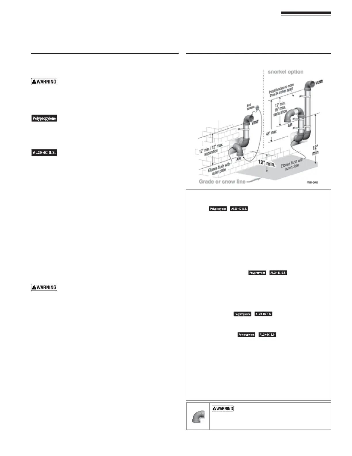
3TEP The air piping must terminate in a down-turned elbow as
shown above. The vent piping must terminate in an elbow
POINTEDOUTWARDORAWAYFROMTHEAIRINLET as shown
above. See illustration above.
3TEP Install vent and air piping between the boiler and the side-
wall openings. Slope horizontal piping downward toward
THEBOILERATLEASTINCHPERFOOT3EE page 32FORGENERAL
guidelines.
3EENOTICESATLEFT
3TEP )NSTALLPIPESUPPORTSEVERYFEETONBOTHTHEHORIZONTAL
and vertical runs. Install a hanger support within 6 inches
OFANYUPTURNINTHEPIPINGORPERVENTPIPEMANUFACTURERS
instructions.
3EENOTICESATLEFT
3TEP !TTACHTHEVENTTERMINATIONEXTERIORPIPING5SEEITHEROFTHE
configurations shown above, as needed to ensure clearance
above grade or snow line. Keep vents/air intake area clear
OFACCUMULATINGSNOW
3TEP 4HEVENTANDAIRPIPESMAYRUNUPASHIGHASFEETWITH
no enclosure. The vent and air pipes must be secured with
braces, and all clearances and lengths must be maintained.
3PACEBRACESNOFURTHERTHANINCHESAPART
3TEP %XTERNALVENTINGGREATERTHANFEETREQUIRESANINSULATED
enclosure around the vent and air pipes. The vent and air
terminations must exit through the enclosure as shown in
the illustration above, maintaining all required clearances.
53% 37%%0 %,"/73 &/2 !,,6%.4
!.$!)20)0).' — DO NOT use short radius
ELBOWSFORVENTORAIRPIPING"OILERPERFORMANCE
COULDBEAFFECTED