Part number 550-142-850/0716
37
FreeStyle
®
WALL MOUNT GAS-FIRED WATER BOILER — Boiler Manual
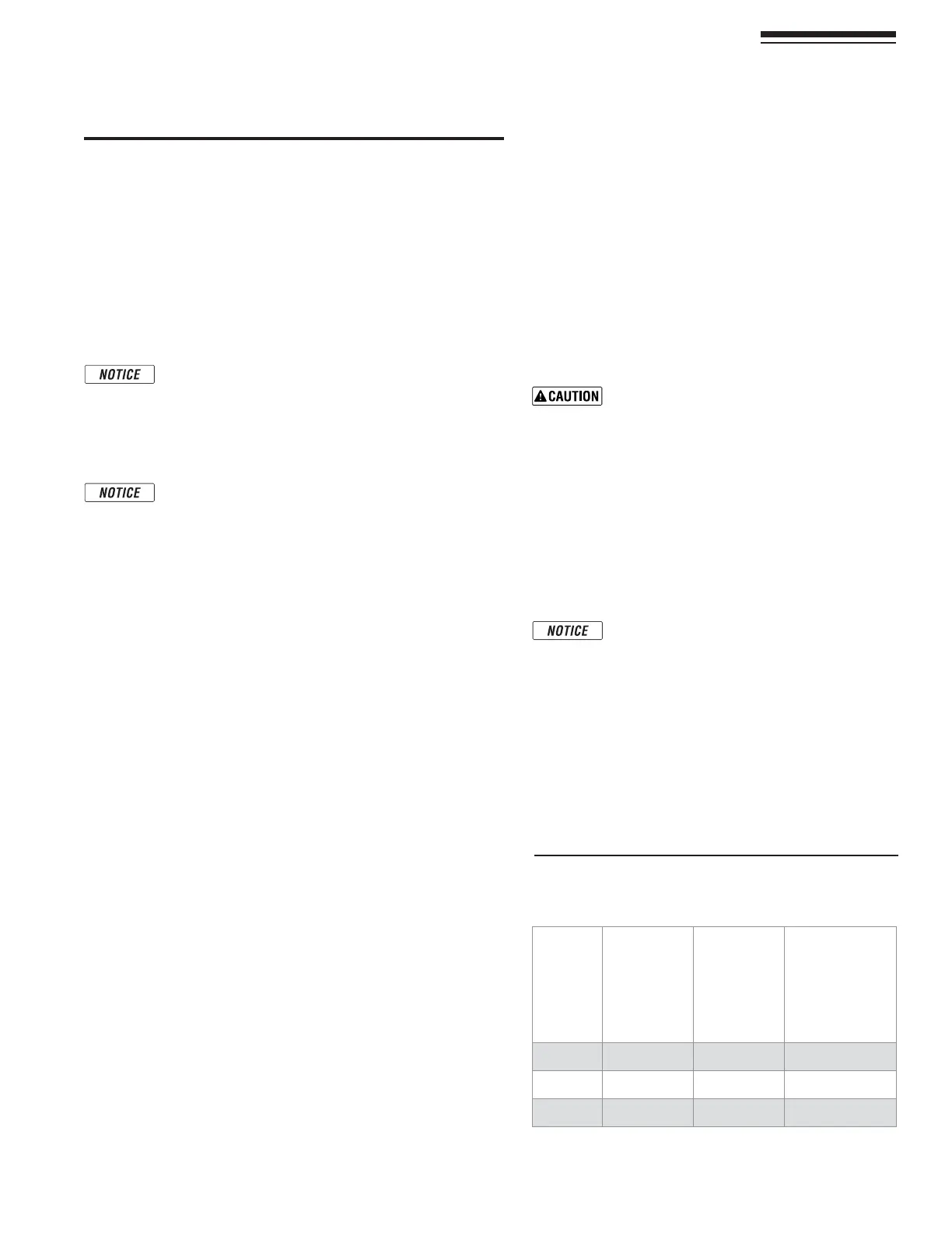
Figure 44 -AXIMUMANDMINIMUMmOWRATESTHROUGH
BOILERHEATEXCHANGER
Boiler
Model
MAX
Flow Rate
20° F
temperature
rise
'0-
MIN
Flow Rate
50° F
temperature
rise
'0-
Flow Rate
Delta T1
protection
67° F
temperature
rise
'0-
&3
7.9 2.9 2.3
&3
12.0 4.3 3.4
&3
15.2 6.1 4.5
17 Primary/Secondary System Piping
System water piping methods
.EARBOILERPIPING
1. Connect boiler to system only as shown in Figure 45, page 38.
The primary/secondary piping shown ensures the boiler loop
WILLHAVESUFlCIENTmOW
2. 3ELECTABOILER LOOP TEMPERATURERISEFROMFigure 47, page 39.
The table indicates the flow and head loss characteristics at that
TEMPERATURERISEANDSUGGESTSPOTENTIALSPEED#IRCULATORSOFOTHER
BRANDSNOTLISTED7ILO!RMSTRONG"'AREACCEPTABLEIFTHEY
MEETTHEmOWANDHEADREQUIREMENTSOFTHEDESIGN
6ERIFY THATTHEboiler loop piping matches closely
with the listed criteria in the NOTICEBELOW)FNEAR
BOILERPIPINGISDIFFERENTCALCULATEHEADLOSSSEPARATELY
USINGHEATEXCHANGERPRESSUREDROPINFORMATIONFROM
Figure 47, page 39 and match to an appropriate pump
speed.
4HEPRESSUREDROPSSHOWNAREFORNEARBOILERPIPINGAS
illustrated in Figure 46, page 38 WITHFEETOFSTRAIGHT
piping. System circulators and zone circulators
3. Install a system circulator or zone circulators as shown in the
piping diagrams in the Primary/Secondary System Piping section
in this manual. These circulators must be supplied by the installer.
3YSTEMORZONECIRCULATORSmOWRATES
1. Size circulators based on the flow rate required to achieve the
temperature drop required. You can closely estimate temperature
RISEORDROPTHROUGHACIRCUITBYUSINGTHEFOLLOWINGFORMULA
where TD is temperature rise (or drop), FLOW is flow rate (in
GPMAND"45(ISTHEHEATLOADFORTHECIRCUIT
FLOW =
"45(
nnnn
4$X
%XAMPLES:
1. #ONSIDERASYSTEMLOOPFORASYSTEMWITHTOTALHEATINGLOADEQUAL
to 210,000 Btuh. The desired temperature drop through the system
piping is 20°F. Then the required flow rate is:
FLOW =
nnnn
X
= GPM
3)-0,)&)%$
&ORTEMPERATUREDROP&,/7-"(
3YSTEMORZONECIRCULATORHEADREQUIREMENT
1. 4HECIRCULATORMUSTBECAPABLEOFDELIVERINGTHEREQUIREDmOW
against the head loss that will occur in the piping.
2. Determine the pipe size needed and the resultant head loss
using accepted engineering methods. See Figure 46, page 38FOR
the head loss through the boiler.
Expansion Tank Location
Figure 45, page 38SHOWTYPICALINSTALLATIONOFTHESYSTEM
expansion tank. It is highly recommended that you locate
the air separator and expansion tank as shown in the sug-
gested piping drawings on pages 37 - 39.
Ensure that the expansion tank size will handle boiler and
SYSTEMWATERVOLUMEANDTEMPERATURE3EETANKMANUFAC-
TURERSINSTRUCTIONSANDRATINGSFORDETAILS!DDITIONALTANKS
MAYBEADDEDTOTHESYSTEMIFNEEDEDTOHANDLETHEEXPAN-
sion. These tanks may be installed by connecting to tees in
the system piping.
Undersized expansion tanks cause system
WATERTOBELOST FROM THERELIEF VALVEAND
makeup water to be added through the fill
VALVE %VENTUALBOILER FAILURECAN RESULTDUE
TOEXCESSIVEMAKEUPWATERADDITION!LWAYS
locate the cold-water fill connection at the
expansion tank. Never locate this elsewhere.
Diaphragm- or bladder-type tank:
2EFERTOFigure 45FORSUGGESTEDPIPINGWHENUSINGADIA-
phragm- or bladder-type expansion tank.
Diaphragm- or bladder-type expansion
tank—Always check pressure and charge
tank with tank removed from system to be
sure reading is accurate. Boiler relief valve is
set for 30 PSIG./PERATINGPRESSUREOFSYSTEM
AFTERTEMPERATURE EXPANSIONABOVECOLDlLL
pressure, should not exceed 24 PSIG to avoid
WEEPINGOFRELIEFVALVE
)NSTALLANAUTOMATICAIRVENTONTOPOFTHEAIRSEPARATORPER
SEPARATORMANUFACTURERSINSTRUCTIONS