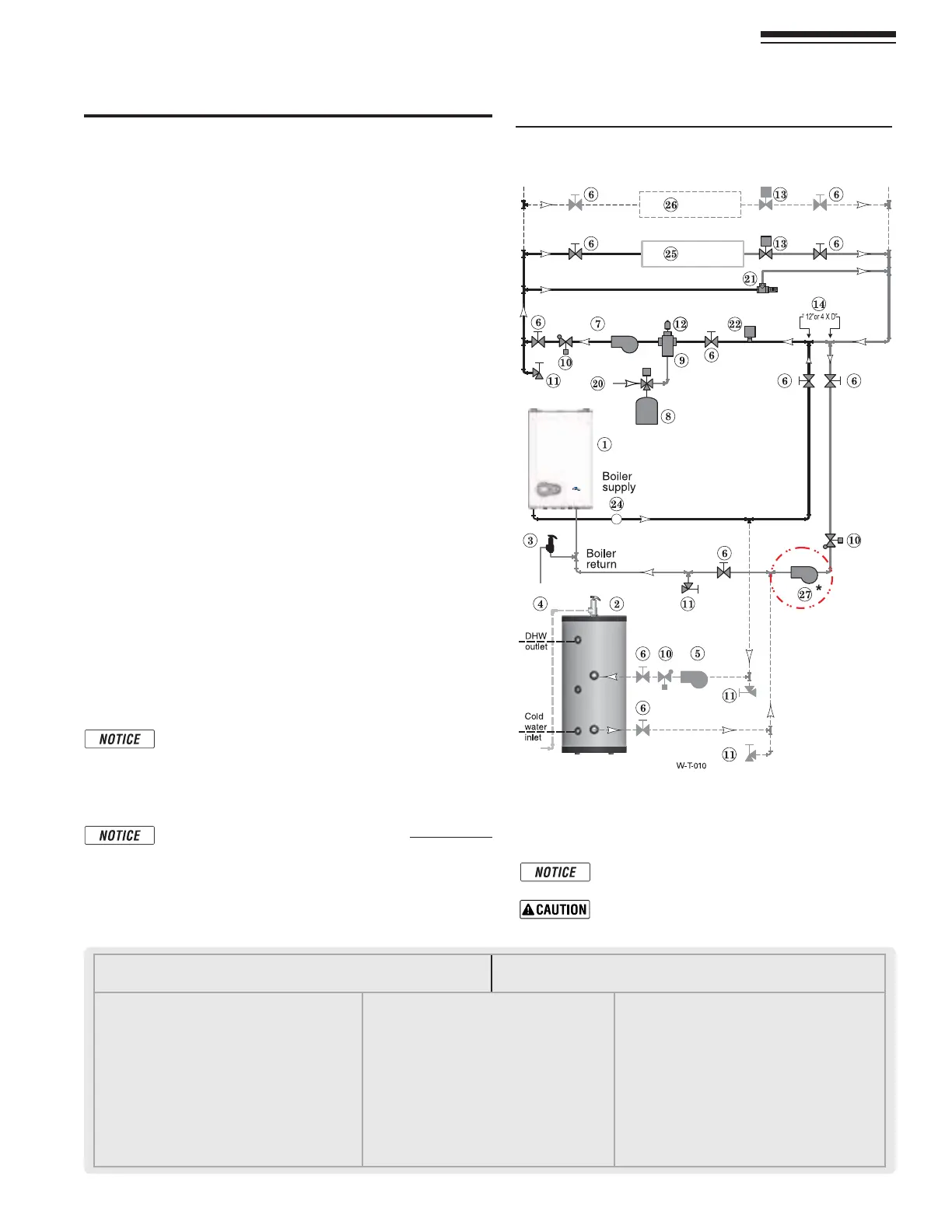
Figure 48:ONEVALVEZONINGPRIMARYSECONDARY
CONNECTIONASYSTEMCIRCULATORISREQUIRED
,%'%.$FORFigure 48.
.OTE4HISISACOMMONLEGENDFORALLPIPINGDIAGRAMS.OTALL
ITEMSLISTEDAPPEARINEVERYlGURE
1 FreeStyle® wall mount boiler
2 Indirect Water Heater, if used
3 Relief valve, supplied by Installer, field piped — MUST be
piped to boiler supply connection — see page 9 for infor-
mation
4 Relief valve piping to drain — see page 40
5 DHW circulator
6 Isolation valves
7 System circulator
8 Expansion tank, diaphragm type, if used
9 Air separator
10 Flow/check valves
11 Purge/drain valves
(Installer supplied)
12 Auto air vent
13 Zone valves
14 Primary/secondary connection (tees no more than
12 inches apart)
15 Expansion tank, closed type, if used (some chiller
systems may use a diaphragm-type expansion tank)
16 Water chiller
17 Check valve
18 Y-strainer
19 Balancing valve
20 Make-up water supply – Use applicable codes to deter-
mine if backflow preventers, pressure reducing valves,
and fill valves may be required
21 By-pass pressure regulator, REQUIRED for zone valve
systems unless other provision is made
22 High limit temperature control
23 Zone circulator
24 Pressure/temperature gauge, supplied with boiler, field piped
25 Heating circuits
26 Additional heating circuits, if any
27 Boiler circulator,
*
(For Heating Only boilers, In the
Combi boiler the circulator is already inside the boiler
jacket).
28 Mixing valve, if any
Part number 550-142-850/0716
41
FreeStyle
®
WALL MOUNT GAS-FIRED WATER BOILER — Boiler Manual
17 Primary/Secondary System Piping (continued)
Zone Valve zoning – primary/secondary
(Shown with optional DHW piping)
See Figure 48.
4HISCONlGURATIONIS FOR ZONEVALVESYSTEMSUSING A BOILER
LOOPCONNECTEDASASECONDARYCIRCUITOFFOFAPRIMARYSYSTEM
loop. Systems whose flow characteristics do not comply with
those listed in Figure 45, page 38 must pipe the boiler loop as a
secondary circuit as show.
3YSTEMSZONEDWITHZONEVALVES-534USEABYPASSPRESSURE
regulator.
)NSTALL ASYSTEMCIRCULATORSUPPLIED BY INSTALLER CAPABLE OF
delivering the proper flow and head as shown.
Expansion Tank required
0ROVIDEASYSTEMEXPANSIONTANKFOLLOWINGTHEGUIDELINESON
pages 37 or 39.
2. DO NOTUSEACLOSEDTYPETANKIFCONNECTINGTOABOILERTHAT
is equipped with an automatic vent.
Domestic Hot Water (DHW) tank, if used
1. $(7DIRECTCONNECTION0IPEFROMTHENEARBOILERPIPINGTO
THE$(7TANKSBOILERCONNECTIONSASSHOWN
2. $(7ASZONE!$(7TANKCANBECONNECTEDASAZONEIFA
DHW tank is NOT already connected to the boiler. To provide
DHW priority operation, use a zone controller. See notices
on page 51TOENSURECOMPLIANCEWITHTHE%NERGY!CT
3. DHW Priority operation—The FreeStyle® CONTROLTURNS OFF
SPACEHEATINGTOTHE(%!4ZONESDURINGDOMESTICWATERHEAT-
INGCALLSONTHE$(7INPUT4HE-!8/.4)-%SETTINGCAN
BEADJUSTEDTOLIMITHOWLONGTHISOCCURS3ETTHE-!8/.
4)-%TOhvTODISABLEDOMESTICPRIORITY3EE page 65FORSET-
ting instructions.
4. )FNOT connecting an indirect water heater, do not use the DHW
input or DHW Circulator output on the FreeStyle® control.
/VERRIDINGTHE/UTDOOR2ESETFUNCTIONBYCONNECTING
space heating zones to inputs and outputs intended
FOR$(7 APPLICATIONS MAYVIOLATESection 303 of
the 2007 Energy Act. See page 127FORCOMPLIANCE
INFORMATIONANDEXEMPTIONS
Wiring the Indirect tank aquastat to the Heating Only
"OILERREFERTO3ECTION&IELD7IRING
Controlling the Zones
1. The FreeStyle® control can be used to control space heating
only, domestic WATERHEATINGONLYORBOTH2EFERTOlELDWIRING
beginning on page 51FORINSTRUCTIONSONWIRINGTOZONEVALVES
2. The boiler and zone valves can also be operated by a
zone controller.
#ONNECTZONEVALVEENDSWITCHESTO(%!4INPUT
#ONNECTSYSTEMCIRCULATORTO(%!4#IRCOUTPUT
5SE ISOLATION RELAYSIF CONNECTINGWIREZONE
VALVEENDSWITCHESTOTHE(%!4INPUT
(See Note,
page 39)