Figure 49 #IRCULATORZONINGPLUSOPTIONAL$(7
PIPING
(See Note,
below)
./4%(Applies to Figures 48, 49 & 50)
Add boiler and tank head loss for pump
sizing.
Part number 550-142-850/0716
42
FreeStyle
®
WALL MOUNT GAS-FIRED WATER BOILER — Boiler Manual
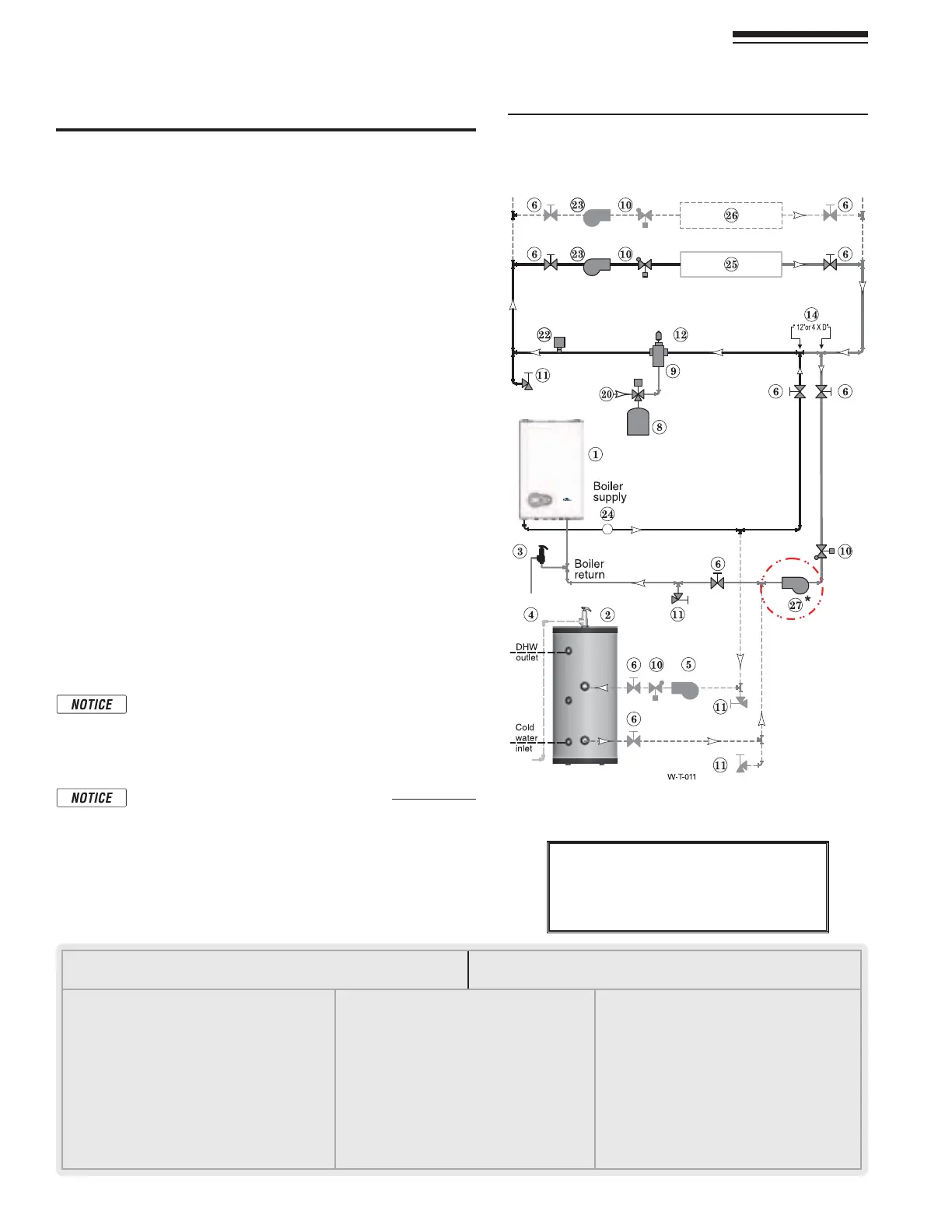
17 Primary/Secondary System Piping (continued)
Circulator zoning – primary/secondary
(Shown with optional DHW piping)
See Figure 49.
1. 4HISCONlGURATIONISFORCIRCULATORZONEDSYSTEMSUSINGABOILER
LOOPCONNECTEDASASECONDARYCIRCUITOFFOFAPRIMARY SYSTEM
loop. Systems zoned with circulators must pipe the boiler loop
as a secondary circuit as show.
)NSTALLASEPARATECIRCULATORSUPPLIEDBYINSTALLERFOREACHZONE
CAPABLEOFDELIVERINGTHEPROPERmOWANDHEADASSHOWN
Expansion Tank required
0ROVIDEASYSTEMEXPANSIONTANKFOLLOWINGTHEGUIDELINESONpages
37 or 39.
2. DO NOTUSEACLOSEDTYPETANKIFCONNECTINGTOABOILERTHATIS
equipped with an automatic vent.
Domestic Hot Water (DHW) tank, if used
1. $(7DIRECTCONNECTION0IPEFROMTHENEARBOILERPIPINGTO
THE$(7TANKSBOILERCONNECTIONSASSHOWN
2. $(7ASZONE!$(7TANKCANBECONNECTEDASAZONEIFA$(7
tank is NOT already connected to the boiler. To provide DHW
priority operation, use a zone controller. See notices on page 51
TOENSURECOMPLIANCEWITHTHE%NERGY!CT
3. DHW Priority operation—The
FreeStyle®CONTROLTURNSOFFSPACE
HEATINGTOTHE(%!4ZONESDURINGDOMESTICWATERHEATINGCALLS
ONTHE$(7INPUT4HE-!8/.4)-%SETTINGCANBEADJUSTED
TOLIMITHOWLONGTHISOCCURS3ETTHE-!8/.4)-%TOhvTO
disable domestic priority. See page 65FORSETTINGINSTRUCTIONS
4. ) F NOT connecting an indirect water heater, do not use the DHW
input or DHW Circulator output on the
FreeStyle® control.
/VERRIDINGTHE/UTDOOR2ESETFUNCTIONBYCONNECTING
SPACEHEATINGZONESTOINPUTSANDOUTPUTSINTENDEDFOR
DHW applications may violate Section 303 of the 2007
Energy Act. See page 127FORCOMPLIANCEINFORMATION
and exemptions.
Wiring the Indirect tank aquastat to the Heating Only
"OILERREFERTO3ECTION&IELD7IRING
Controlling the Zones
1. The FreeStyle® control can be used to control space heating only,
DOMESTICWATERHEATINGONLYORBOTH2EFERTOlELDWIRINGBEGIN-
ning on page 51FORINSTRUCTIONSONWIRINGTOCIRCULATORS
2. The boiler and circulators can also be operated by a zone
controller.
,%'%.$FORFigure 49 and Figure 50
.OTE4HISISACOMMONLEGENDFORALLPIPINGDIAGRAMSNOT
ALLITEMSLISTEDAPPEARINEVERYlGURE
1 FreeStyle® wall mount boiler
2 Indirect Water Heater, if used
3 Relief valve,
supplied by Installer, field piped — MUST
be piped to boiler supply connection — see page 9 for
information
4 Relief valve piping to drain — see page 40
5 DHW circulator
6 Isolation valves
7 System circulator
8 Expansion tank, diaphragm type, if used
9 Air separator
10 Flow/check valves
11 Purge/drain valves
(Installer supplied)
12 Auto air vent
13 Zone valves
14 Primary/secondary connection (tees no more than
12 inches apart)
15 Expansion tank, closed type, if used (some chiller
systems may use a diaphragm-type expansion tank)
16 Water chiller
17 Check valve
18 Y-strainer
19 Balancing valve
20 Make-up water supply – Use applicable codes to deter-
mine if backflow preventers, pressure reducing valves,
and fill valves may be required
21 By-pass pressure regulator, REQUIRED for zone valve
systems unless other provision is made
22 High limit temperature control
23 Zone circulator
24 Pressure/temperature gauge, supplied with boiler, field
piped
25 Heating circuits
26 Additional heating circuits, if any
27 Boiler circulator,
*
(For Heating Only boilers, In the
Combi boiler the circulator is already inside the
boiler jacket).
28 Mixing valve, if any