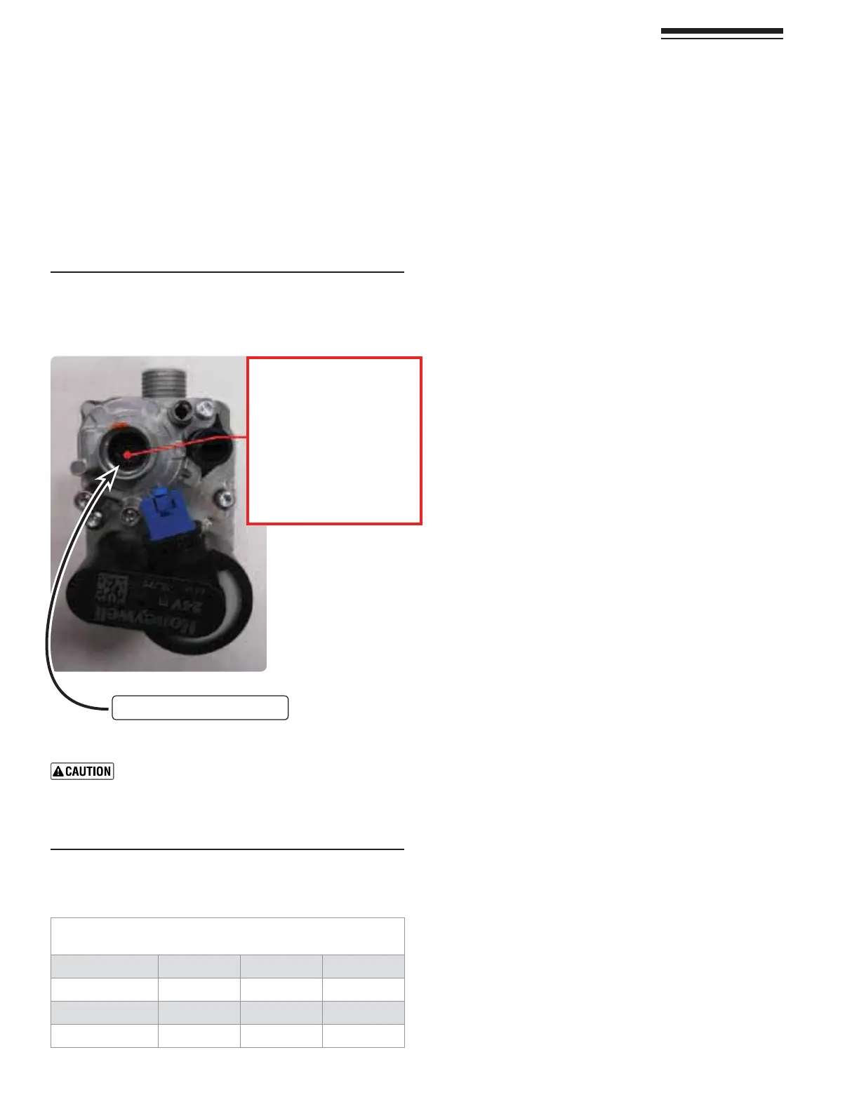
Figure 100Offset aDJUSTMENTSCREWnn
/.,9FORUSEBYAQUALIlEDTECHNICIANUSING
CALIBRATEDCOMBUSTIONTESTINSTRUMENTS
Part number 550-142-850/0716
74
FreeStyle
®
WALL MOUNT GAS-FIRED WATER BOILER — Boiler Manual
.ATURAL'AS!CCEPTABLE#OMBUSTION2ANGE
-INIMUM2ATEAFTERMINUTESFROMCOLD
Boiler Model
CO/(PPM) CO
2
NG % CO
2
LP %
&3
20
n
n
&3
20
n
n
&3
7
n
n
At Minimum Rate:
1. !DJUSTTHEBOILERTOMINIMUMOUTPUTANDALLOWTHEBOILER
to stabilize.
2. .OWADJUSTTHEOFFSETPRESSURESETTINGFigure 100 - cup B)
Torx (T-40 male driver) until the CO
2
is at the correct SET-
TING LEVEL (see Figure 101), confirm that the CO/CO
2
ratio is within limits (clockwise to increase gas).
28 (continued)
Re-check the Minimum Rate
3. 4URNOFFTHEBOILERANDTHENTURNITBACKONANDPUTIN4EST
-ODEATMAXIMUMFORMINUTETHENREDUCElRINGRATE
HIGHlREFORMINUTES2EDUCETOMINIMUMANDRECHECK
the minimum rate output ensuring the CO
2
setting level has
remained unchanged and confirm that the CO/CO
2
ratio
is within limits.
4. In the event that the CO
2
setting level with an acceptable
CO/CO
2
ratio cannot be obtained please contact your
Williamson-Thermoflo representative.
5. Should you require any assistance during the set up pro-
cedure contact your Williamson-Thermoflo representative
IFTHEPROBLEMCANNOTBEADDRESSEDWITHTHEINFORMATION
provided in this manual.
❏#HECK(EATEXCHANGERANDVENTSEALS
1. Operate the boiler on HIGH fire.
2. !LEAKWOULDAPPEARASVAPORONTHESURFACEOFTHEMIRROR
3. )FTHEREISANYINDICATIONOFALEAKATANYJOINTIMMEDIATELY
shut down the boiler.
a. )FPOSSIBLETIGHTENTHERETAININGSCREWSORNUTSWITHOUT
over-tightening).
b. )FTHIS DOES NOT CORRECTTHEPROBLEMDISASSEMBLE THE
components where the leak appeared. Use the proce-
DURESGIVENINTHE-AINTENANCESECTIONOFTHISMANUAL
c. When disassembling components, inspect gaskets to see
IFTHEREISDAMAGE2EPLACEANYDAMAGEDGASKET
d. #ONTACTYOUR7ILLIAMSON4HERMOmOREPRESENTATIVEIF
THEPROBLEMCANNOTBEADDRESSEDWITHTHEINFORMATION
provided in this manual.
❏#HECKIGNITIONSYSTEMSAFETYSHUTOFFDEVICE
1. !FTERTHEBOILERHASBEENINSTALLEDTURNOFFTHEBOILER
2. 3HUTOFFTHEMANUALGASVALVELOCATEDONTHEGASLINETOCUT
mOWOFFUELTOTHEBOILER
3. Turn on the boiler. It will start to ignite and a “d3” code will
mASH!FTERTHEhd3”CODEmASHFORSOMETIMETHEBOILERWILL
go into a Lockout condition and a “!” code will show in
the display. It means that the boiler tried to ignite without
success (code “d3” FOR THREE TIMES AND WHEN INTO
Lockout mode(code “!”). This means that the ignition
SYSTEMSAFETYDEVICEWORKEDPROPERLY
4. Open the manual gas valve located on the gas line to resume
FUELSUPPLYTOTHEBOILER
5. Hit the “Reset” button once to Clear the Lockout code “!”.
Figure 101Minimum rate combustion values –
measured values must be within the ranges
given below
!DJUSTINSTEPSOFNOMORETHANOFATURNAND
WAITMINUTEAFTEREACHADJUSTMENTTOALLOWTHE
SETTINGTOSTABILISE4URNINGTHESCREWTOOFARWILL
cause the adjustment to reverse behavior.
/FFSETADJUSTMENTB
Offset Regulating screw
Test at MIN. Power 00%
Turn clockwise (open gas)
Turn counter-clockwise
(close gas)