Part number 550-142-850/0716
84
FreeStyle
®
WALL MOUNT GAS-FIRED WATER BOILER — Boiler Manual
32 Troubleshooting(continued)
FreeStyle
®
Control diagnosis
1. The FreeStyle® boiler controlISEQUIPPEDWITHANADVANCEDSELFDIAGNOSISSYSTEM)NCASEOFABOILERFAULTTHEDISPLAYWILLmASH
TOGETHERWITHTHEFAULTSYMBOLSEE4ABLEORINDICATINGTHEFAULTCODE
2. #ERTAINFAULTSCAUSEPERMANENTBOILERSHUTDOWNSMARKEDWITHTHELETTERhA” see 4ABLE): to restore operation, press the RESET
button (Item 6 - Figure 74, page 60FORSECONDOR2%3%4ONTHEOPTIONALREMOTETIMERCONTROLIFINSTALLEDIFTHEBOILERFAILS
TOSTARTITISNECESSARYTOlRSTLYELIMINATETHEFAULT
3. /THERFAULTSINDICATEDWITHTHELETTERhF”, see 4ABLE) cause temporary shutdowns that are automatically reset as soon as the
VALUERETURNSWITHINTHEBOILERSNORMALOPERATINGRANGE
Protection and error conditions
1. Several checks are included to protect the boiler and its environment. Severe error will cause a lockout condition which can only
BECLEAREDBYTHERESETKEYATTHEBOILERFRONTPANEL
2. .ONSEVEREERRORSFAULTSWILLRESETASSOONASTHECAUSEOFTHEPROBLEMDISAPPEARSCORRECTSTHEMSELVES
3. .UMBEROFRESETACTIONISLIMITEDTOINHOURS"YPOWERINGOFFONITISPOSSIBLETORESETTHISLIMITATIONINTHISWAYANOTHER
5 reset per 24 hour can be done.
4. Error codes can be divided in 2 groups:
a. Lock-out condition codes – “AvCODESWHICHBLOCKSTHEHEATDEMAND0RESSRESETBUTTONFORSECONDTORESET
b. Blocking condition codes – “F” codes: (cause temporary shutdowns that are automatically reset as soon as the valve returns
within the boilers normal working range)
Lock out condition codes
Lock out condition is given with the capital “A” (alarm) on the status display and error code on the
TEMPERATUREDISPLAY4HEMEANINGOFTHEERRORNUMBERSAREASFOLLOW
-AKESURETODETERMINETHECAUSESOFOUTAGES$ONOTLEAVETHEBOILEROPERATINGWITHOUTACOM-
PLETEDIAGNOSIS
Table 3 FreeStyle
®
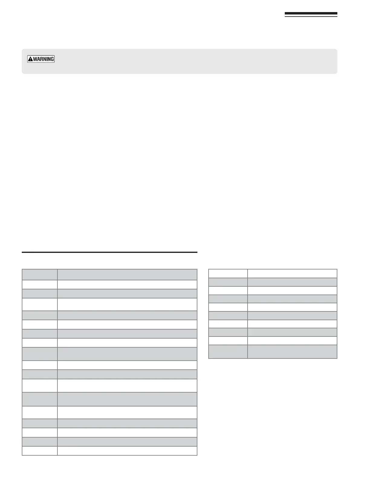
LISTOFh!vCODES
%RRORCODE $ESCRIPTION
A01 Lockout indication
A02
A03
High limit protection: pump does not run or no
water circulation
A04 F07 repeated 3 times in the last 24 hours
A05 No frequency feedback from fan after 1 hour
A06
A16 Outside sensor is not connected
A23
Nominal water pressure not reached within
maximum allowed time
A24
A26 F40 repeated 3 times in the last hour
A41
Temperature sensor not or bad connected to
the pipe (CH mode)
A42
Too high difference between two CH supply water
temperature sensors
A44
Temperature sensor not or bad connected to
the pipe (DHW mode)
A61 Flame circuit error
A62 Gas valve circuit
A63 E2 prom error
A65 ADC circuit error
!BBREVIATION $ESCRIPTION
ADC Analog Digital Converter
CH Central Heating
DHW Domestic Hot Water
LP
LWCO Low Water Cut Off
MMI Machine Interface- Control Interface
OTC Outdoor Temperature Sensor
PCB Printed Circuit Board - Control board
PWM
Pulse width modulation - Used for
modulating pumps and motors