for the system. The areas that the sensors monitor
are defined as Zone 1 (cab interior) and Zone 2
(engine compartment). The control module has lights
assigned to each zone that will illuminate if a sensor
detects a trace level leak (between 20% and 50%
LFL), Or a dangerous leak (above 50% LFL), or if a
sensor is disconnected or malfunctioning.
•
Green: System is functioning properly.
•
Amber: If the system detects that either of the
sensors has been disconnected or has
malfunctioned, an amber light next to the
"FAULT" indicator for that zone will illuminate.
•
Red: If either sensor detects gas fumes at a
concentration greater than 20% (2.5% gas in
air by volume), the small red light next to the
"DANGER" indicator for that zone will flash.
After approximately 15 seconds, the large
green light on the alarm panel will switch off,
the red light will illuminate, and the buzzer will
sound. All alarm indicators will remain on as
long as fumes are detected.
The control module also has buttons used to test or
reset the control module and silence the buzzer after
an alarm.
•
TEST: Press the "TEST" button to test the LED
and output operation.
•
Reset/Silence: If an alarm has been activated,
the "RESET/SILENCE" button will silence the
buzzer.
See
Table 19.2 for the functions of all lights and
buttons on the control module.
Fireboy Control Module Functions
Item Display Function Action Required
Interior OK LED (green) Illuminated
Interior sensor is detected, signal
is OK, and system power is on.
None required.
Interior Fault LED (yellow) Illuminated
Interior sensor is not detected, or
there is a signal malfunction.
Have the system checked
immediately.
Interior Danger LED (red) Illuminated
Interior sensor is reading an
amount of gas greater than 20%
LFL.
Suspend vehicle operation
immediately and follow alarm
procedures.
Test Button —
Cycles the LEDs and triggers the
relay temporarily.
Press and hold for one minute to
activate a test of all control
module components.
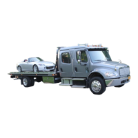
f470673a06/13/2022
1
2
3 4
1. Sensor
2. Buzzer
3. Green Light
4. Red Light
Fig. 19.8, Alarm Panel (overhead console)
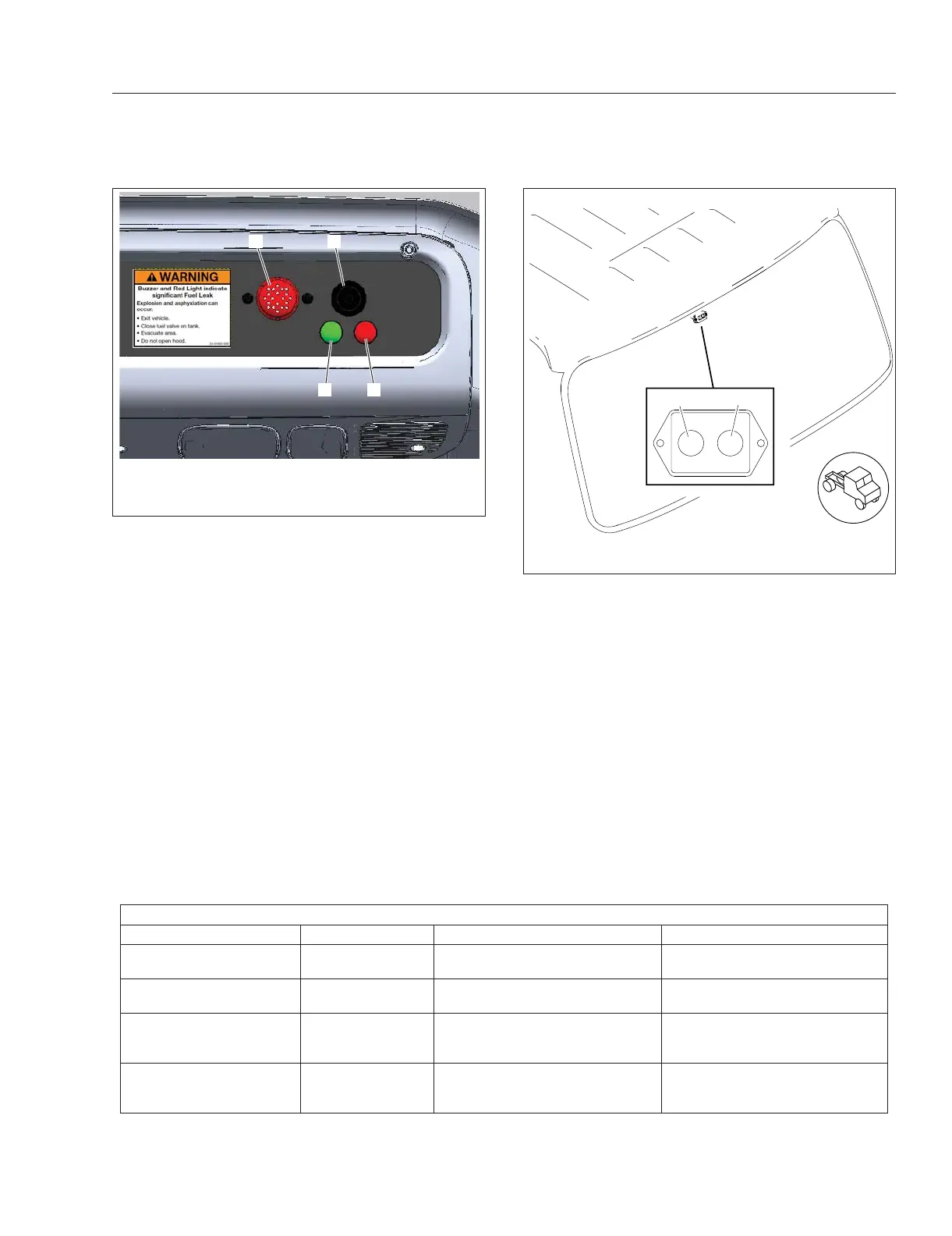
09/15/2015 f470674
12
1. Green Light 2. Red Light
Fig. 19.9, Alarm Panel (upper windshield)
Natural Gas Vehicle Information
19.8