25 Locust St, Haverhill, Massachusetts 01830 • Tel: 800/252-7074, 978/374-0761 • FAX: 978/521-1839
e-mail: sales@freqdev.com • Web Address: http://www.freqdev.com
Section 2
6
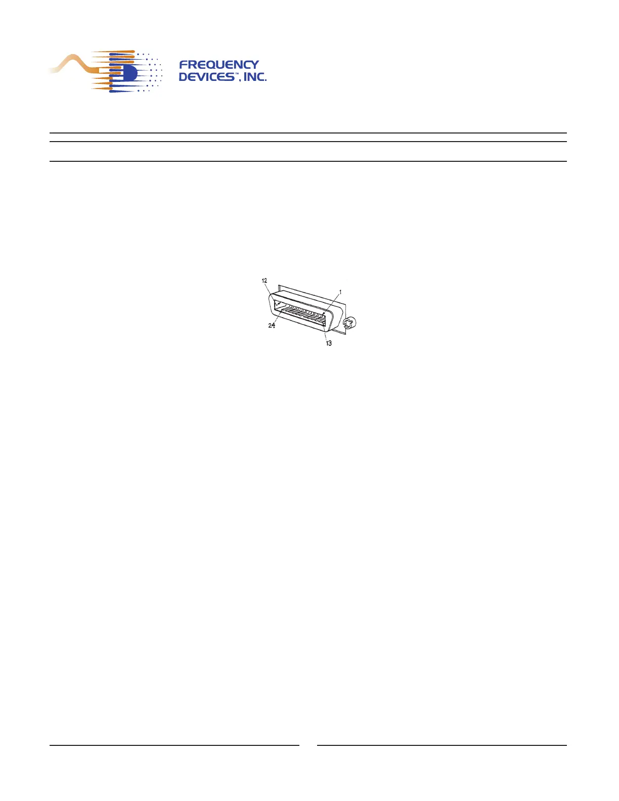
Figure 2.2 IEEE Connector Identification
The signals to be filtered are introduced to the Model 9002 via front and rear panel coaxial BNC connectors as seen
in Figure 2.1a. Input impedance is one megohm resistive shunted by a fixed 47 picofarad capacitance. Signal inputs
can be up to 20 volts p-p without clipping.
The filtered outputs are also supplied a BNCs on the front and rear panels. The output amplifiers are protected by
current limiting resistors. Outputs take on the same AC or DC coupling as the inputs, though output signal levels can
be independently adjusted.
Inputs are operator programmable by either single-ended or differential input, and may be either AC or DC coupled.
The input is overload protected via diode clamping to the power supply.
Precise circuit configurations for both input and output are given in the Product Data Sheet (Appendix A).
2.3 - Filter Properties
The Model 9002 is configured with two standard filters that are specified at the time of ordering. These filters are
chosen from the six models available, ten lowpass and five highpass. Table 2.1 lists the filter models available:
Model 9002
Instrument Description
Pin Definition Pin Definition Pin Definition
1 D101 5 EOI 12 Shield-Chassis Ground
2 D102 17 REN 18 P/O Twisted Pair with Pin 6
3 D103 6 DAV 19 P/O Twisted Pair with Pin 7
4 D104 7 NRFD 20 P/O Twisted Pair with Pin 8
13 D105 8 NDAC 21 P/O Twisted Pair with Pin 9
14 D106 9 IFC 22 P/O Twisted Pair with Pin 10
15 D107 10 SRQ 23 P/O Twisted Pair with Pin 11
16 D108 11 ATN 24 Isolated Digital Ground