25 Locust St, Haverhill, Massachusetts 01830 • Tel: 800/252-7074, 978/374-0761 • FAX: 978/521-1839
e-mail: sales@freqdev.com • Web Address: http://www.freqdev.com
Section 1
3
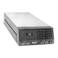
Model 9002
Introduction
Section 1
Introduction
1.1 - Device Description
This system is intended for use as an electronic filter for applications in the Hertz to hundred of kiloHertz range. It can
exhibit either highpass or lowpass characteristics and simulates any two of six possible mathematical configurations:
The filter type in each channel is selected at time of purchase and is installed at the factory. If changing of the filter
type is desired, contact your local FDI representative.
The two channels in the unit are entirely independent. They can by externally interconnected to create a bandpass
filter with adjustable upper and lower cutoff points. The unit is voltage protected at the input up to 100 V and current
limited at the output to 100 mA.
Each channel can be programmed to eight separate configurations, becoming eight distinct filters. The programming
can be done at the front panel or via an IEEE-488 interface to a remote controller. The configurations are stored in
nonvolatile memory for recall or change at any time.
1.2 - Applications
The Model 9002 filter can be used in any application where frequency filtration is required. A wide range of frequen-
cies, input voltage ranges, and pre- and post-amplification stages enables these filters to interconnect with most
laboratory equipment as well as standard audio and radio frequency test equipment. Since the filter characteristics
can be precisely defined, the Model 9002 is an excellent development instrument for perfecting filter spectra in
analytic, electronic, biomedical, and physics applications.
1.3 - System Interconnection
The Model 9002 may be considered to be two, independent electronic frequency filters with either highpass or
lowpass properties. The channels may be cascaded to produce a bandpass filter. Use of the filter is the same as
any R-L-C filter network, with the following exceptions:
1. Your signal source is not loaded by the filter.
2. The output has a fixed, 50 ohm resistive impedance.
3. Signal levels can be controlled at the input and output by means of built-in
variable gain operational amplifiers.
Lowpass: Butterworth, Elliptic, Bessel, Constant Delay
Highpass: Butterworth, Elliptic