25 Locust St, Haverhill, Massachusetts 01830 • Tel: 800/252-7074, 978/374-0761 • FAX: 978/521-1839
e-mail: sales@freqdev.com • Web Address: http://www.freqdev.com
Section 2
8
Input Impedance
2
Single ended 1 M Ωpar. with 47 pF to analog grd.
Differential 1 M Ωpar. with 47 pF to analog grd. on each side
Input Signal Level
± 10V peak for linear system operation
Protected to withstand 115 volts AC at input without damage
Common Mode Rejection
60 db typical, 50 db minimum, DC to 100 kHz
Common Mode Voltage range Full signal swing (±-10V)
Output Characteristics
Impedance 50 ohms, resistive
2
Current maximum ±100 mA into a 50 ohm load
Offset Voltage ±2 mV, for 0 db Pre- and Post-gain
Filter Bypass mode
System maintains all characteristics of the chosen filter except the passband is flat with a
small signal bandwidth of 1 mHz (-6 db) and full power bandwidth of 125 kHz.
2.4.2 - Physical
Height 3.5 in; 90 mm
Width 8.5 in; 216 mm
Depth 17 in; 432 mm
Mounting Benchtop or 19 inch rack mount
2.4.3 - Environmental
Operating Temperatures
Full specifications and resolution 20 to 30° C; 68 to 86° F
Reduced specifications 0 to +40° C; 32 to 104° F
Storage Temperature -25 to +55° C; -13 to +131° F
Relative Humidity 95% max., without condensation
Altitude Up to 15,000 feet; 4500 meters
1
10,400.0 Hz-204,800.0 Hz @ 200 Hz increments for 9002-200 kHz
2
See the Product Data Sheet (Appendix A) for circuit details.
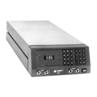
Model 9002
Instrument Description