25 Locust St, Haverhill, Massachusetts 01830 • Tel: 800/252-7074, 978/374-0761 • FAX: 978/521-1839
e-mail: sales@freqdev.com • Web Address: http://www.freqdev.com
Section 5
27
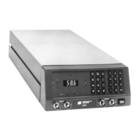
Model 9002
Remote Control Operation
Perform the following steps to calculate the Code $06 sequence for the sample configuration given above.
Step # Action to be Taken
1 Get Byte 1
1a Command Code = $06
2 Get Byte 2
2a Get selected channel # code
Channel selected = Ch. 1
Channel code = $00
3 Get Byte 3
3a Get selected filter configuration # code
Configuration selected = Config. 4
Configuration Code = $04
4 Get bytes 4 - 7 to set filter signal parameters
4a Calculate range (R) and Base Result
Base Result = DCF/R = for that R which yield the largest
number between 1 and 1024
Desired Corner Frequency (DCF) = 100
4b Get Range Code (R2-R0)
for R = 0.1, R2 - R0 = 110, See Table 5.8
4c Calculate Frequency Base (F)
F = Base Result - 1
F = 1000 - 1
F = 999
4d Get Frequency Base Code (F9 - F0)
Convert F (Frequency Base ) to a 10-bit binary
999 = 1111100111 = F9(MSB) - F0(LSB).
4e Verify F & R results by calculating PCF
(Programmed Corner Frequency)
PCF = (F + 1) x R = (999 + 1) x 0.1 = 100
If PCF equals the DCF within the resolution for that range, then the results
are correct.
Determining the Base Result for the Example
DCF R Base Result
100 0.1 1000; Select R - 0.1 & Base Result = 1000
100 0 100
100 10 10
100 100 1