S90-010 CS (APR 08) FRICK
QUANTUM™ COMPRESSOR CONTROL PANEL
Page 32 COMMUNICATIONS SETUP
The Query
The function code in the query tells the addressed
Quantum™ what kind of action to perform. The data bytes
contain any additional information that the Quantum™ will
need to perform the function. For example, function code
03 will query the Quantum™ to read holding registers and
respond with their contents. The data field must contain
the information telling the Quantum™ which register to
start at and how many registers to read. The error check
field provides a method for the Quantum™ to validate the
integrity of the message contents.
The Response
If the Quantum™ makes a normal response, the function
code in the response is an echo of the function code in the
query. The data bytes contain the data collected by the
Quantum™, such as register values or status. If an error
occurs, the function code is modified to indicate that the
response is an error response, and the data bytes contain
a code that describes the error. The error check field
allows the master to confirm that the message contents
are valid.
Data Field
The data field is constructed using sets of two
hexadecimal digits, in the range of 00 to FF hexadecimal.
These can be made from a pair of ASCII characters.
The data field of messages sent from a master to the
Quantum™ devices contains additional information which
the Quantum™ must use to take the action defined by the
function code. This can include items like discrete and
register addresses, the quantity of items to be handled,
and the count of actual data bytes in the field.
For example, if the master requests a Quantum™ to read
a group of holding registers (function code 03), the data
field specifies the starting register and how many registers
are to be read.
If no error occurs, the data field of a response from a
Quantum™ to a Master contains the data requested. If an
error occurs, the field contains an exception code that the
Master application can use to determine the next action to
be taken.
Error Checking
When data is transmitted to and from the Quantum™
Controller, each message has an Error Checking value
appended to the end of the message. Because the
Quantum™ utilizes Modbus ASCII protocol, Longitudinal
Redundancy Check, or LRC, is used as the method for
verifying that the message sent from the transmitting
device, was properly received by the receiving device.
The Longitudinal Redundancy Check (LRC) field is one
byte, containing an eight-bit binary value. The LRC value
is calculated by the transmitting device, by adding together
successive eight-bit bytes of the message, discarding any
carries, and then two's complementing the result. It is
performed on the ASCII message field contents excluding
the colon character that begins the message, and
excluding the CRLF pair at the end of the message. The
LRC is then appended to the message as the last field
preceding the CRLF (Carriage – Line Feed) characters.
Each new addition of a character that would result in a
value higher than 255 decimal simply rolls over the field's
value through zero. Because there is no ninth bit, the carry
is discarded automatically.
The receiving device recalculates an LRC during receipt of
the message, and compares the calculated value to the
actual value it received in the LRC field. If the two values
are not equal, an error results.
ASCII Framing
In ASCII mode, messages start with a colon ( : ) character
(3A hex), and end with a carriage return-line feed (CRLF)
pair (0D and 0A hex).
The allowable characters transmitted for all other fields are
hexadecimal 0 - 9, A - F.
All Quantum™ panels connected to the network monitor
the network bus continuously for the colon character.
When one is received, each Quantum™ decodes the next
field (the address field) to find out if it is the addressed
device.
A Modbus message is placed by the transmitting device
into a frame that has a known beginning and ending point.
This allows receiving devices to begin at the start of the
message, read the address portion and determine which
device is addressed, and to know when the message is
completed. Partial messages can be detected and errors
can be set as a result.
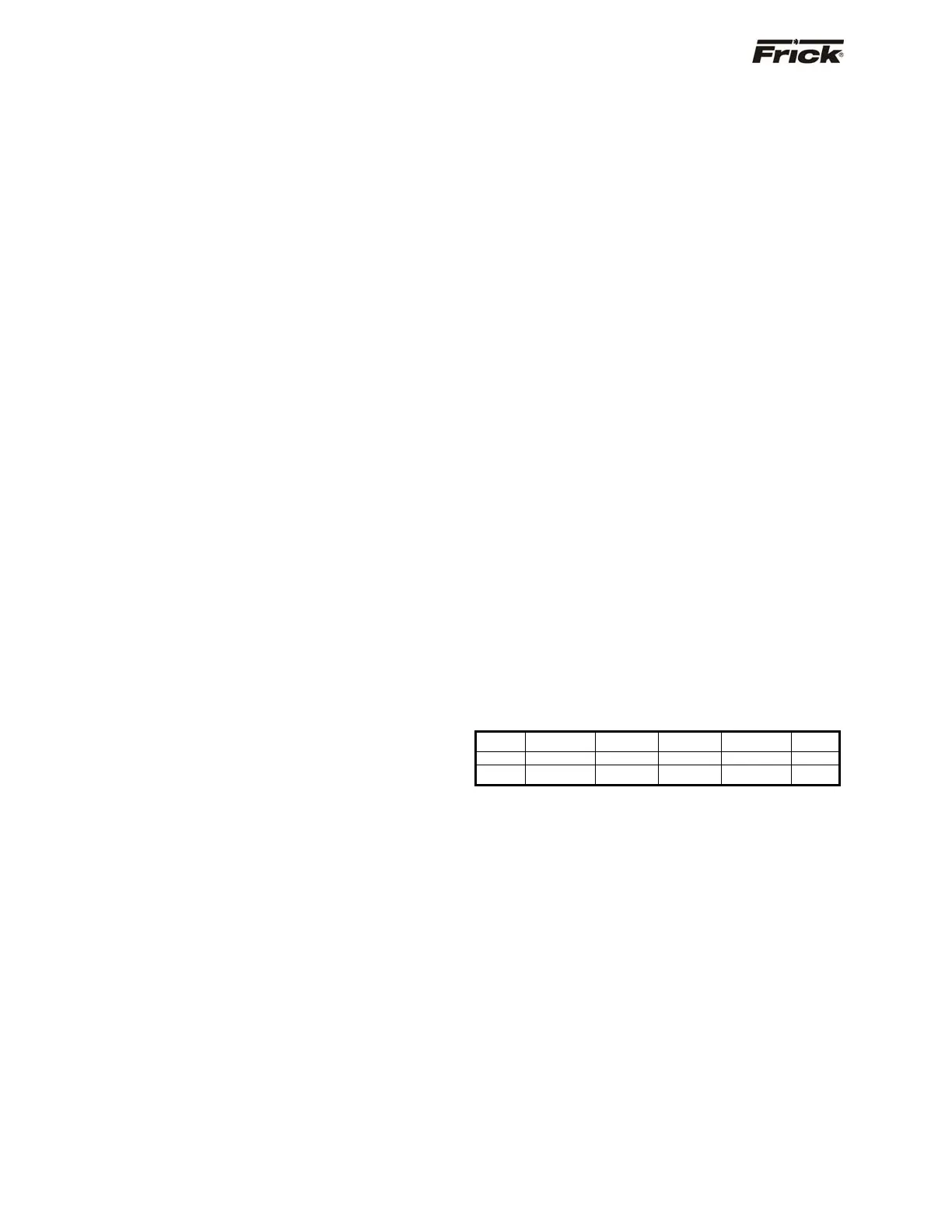
A typical message frame as sent by the Master is shown
below.
START ADDRESS FUNCTION DATA LRC CHECK END
: 01 03 00870001 74 CRLF
1 CHAR 2 CHAR 2 CHAR 8 CHAR 2 CHAR 2 CHAR
Where
: = Start of Message
01 = Quantum™ ID
03 = Read Function
00 = H.O. address (hex)
87 = L.O. address (hex)
00 = H.O. # of Data Registers
01 = L.O. # of Data Registers
74 = Error Correction Code
CRLF = Carriage Return – Line Feed