S90-010 CS (APR 08) FRICK
QUANTUM™ COMPRESSOR CONTROL PANEL
Page 38 COMMUNICATIONS SETUP
YORK ISN DATA ACCESS
ISN Revision 7
The Quantum™ panels Com-2 serial port is connected to
a ISN’s RS-485 serial port that is configured for York Talk
communications. Wire the ISN’s –RX / -TX to the
Quantum™ P12 pin 1 (-RX / -TX) and wire the ISN’s +RX /
+TX to the Quantum™ P12 pin 2 (+RX / +TX). Check that
the ISN communication protocol has been selected from
the Panel Setup – Change Communications screen and
that the baud rate of Com-2 and the panel ID number
coincide with the setup of the ISN device. The Quantum™
ID number is used for the ISN Node number.
The data exchanged with the ISN is found on pages (P) in
feature (F) 54 of the ISN. All temperatures are in degree C
and all pressures are in PSIA. A mode such as Slide Valve
mode is sent as an integer value that represents the mode
it is in. For example, a zero (0) is sent if it is in manual, or
a 1 is sent if it is in automatic, or a 2 is sent if it is in
remote. When changing a setpoint, the setpoint range is
checked to see if the received value is an allowed setting.
If it is not allowed, the setting is not changed.
If the compressor is to be remotely controlled and the
settings being sent from the ISN are not wanted to be
used for control, then two digital bytes must be set to a
one (1) to tell the Quantum to ignore the control settings
being sent to it from the ISN. Sending a one (1) in the
Start/Stop Enable digital byte from the ISN will signal the
Quantum to ignore the Start/Stop digital value received
from the ISN. Sending a one (1) in the Change Setpoints
Enable digital byte from the ISN will signal the Quantum to
ignore the setpoint values received from the ISN.
If the compressor is to be remotely controlled from the ISN
settings, then the compressor must be in remote to accept
the start and stop commands that are sent through serial
communication and the Start/Stop Enable received from
the ISN must equal zero (0). To change a setpoint the
Change Setpoint Enable received from the ISN must equal
zero (0)
Note: The Quantum can still communicate to an ISN
panel that has revision 6 software if the baud rate is set for
1200, 2400, or 4800.
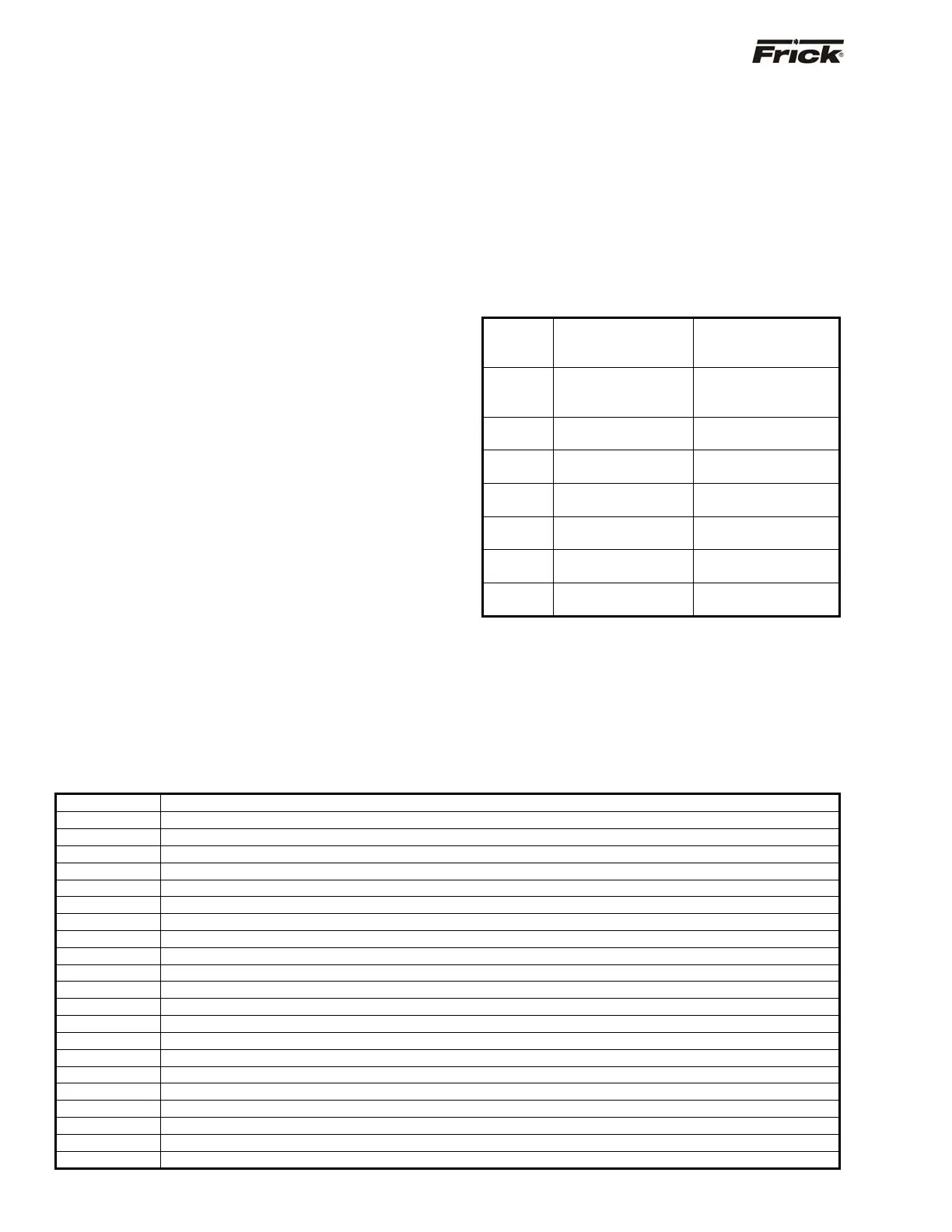
Quantum™ Receiving from ISN:
4 byte Analogs A1-A4
4 x 1 byte Digitals D1-D4
P03
Analog 1
Capacity.Sp
Capacity setpoint for
the current capacity
Control
P04
Analog 2
Amps.Force_Unl.Sp
High Motor Amps
Force Unload
setpoint
P05
Analog 3
Amps.Stop_Load.Sp
High Motor Amps
Stop Load setpoint
P06
Analog 4
Spare
P07
Digital 1
Start Remote Start/Stop
P08
Digital 2
Start/Stop Enable
0 = Enabled
1 = Disabled
P09
Digital 3
Change Setpoints
Enable
0 = Enabled
1 = Disabled
P10
Digital 4
Spare
Quantum™ Sending to ISN:
25 x 4 byte Analogs A01-A25
20 x 1 byte Digitals D01-D20
10 x 1 byte Codes (OC) OP CODE 01 - OP CODE 10
14 x 4 byte Analogs A26-A39
5 x 1 byte Digitals D21-D25
Total = 191 data bytes
Following is a listing of the Quantum™ data that is sent to the ISN and the resulting ISN address:
ISN Address Description of Data
P11-A01 Suction Temperature
P12-A02 Discharge Temperature
P13-A03 Oil Temperature
P14-A04 Oil Separator Temperature
P15-A05 Leaving Process Temperature
P16-A06 Oil Pressure
P17-A07 Filter Differential Pressure
P18-A08 Discharge Pressure
P19-A09 Suction Pressure
P20-A10 Balance Piston Pressure
P21-A11 System Discharge Pressure
P22-A12 Calculated Slide Valve Position
P23-A13 Slide Stop Position
P24-A14 Motor Current Amps
P25-A15 Motor Full Load Amps %
P26-A16 Entering Process Temperature
P27-A17 User-Defined Pressure/Temperature #1 Monitor only
P28-A18 High Motor Amps Force Unload Setpoint
P29-A19 High Motor Amps Stop Load Setpoint
P30-A20 Anti Recycle Delay Setpoint
P31-A21 Slide Valve Minimum Start Setpoint