FRICK
QUANTUM™ COMPRESSOR CONTROL PANEL S90-010 CS (APR 08)
COMMUNICATIONS SETUP Page 7
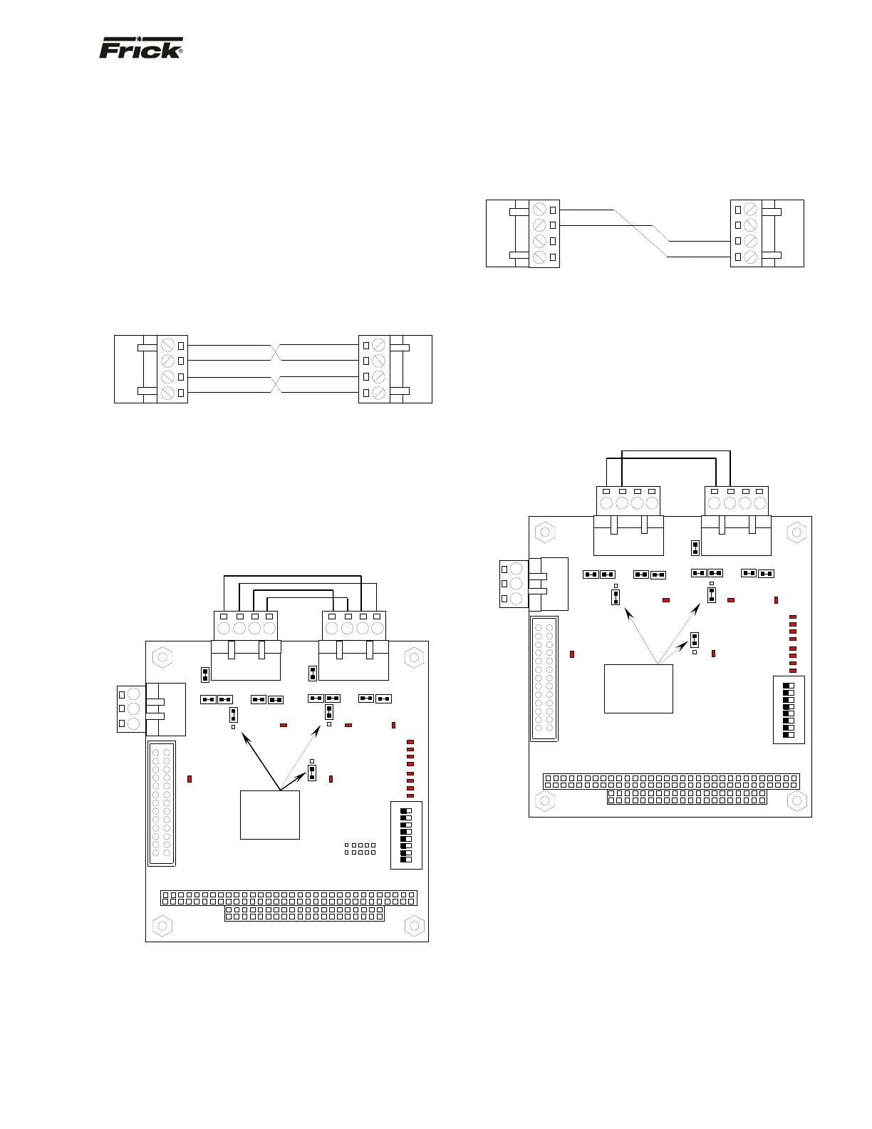
COMMUNICATIONS LOOPBACK TEST
With version 5.0x Quantum™ software, a method of
testing the onboard RS-422 and RS-485 communications
ports was developed. By utilizing a loopback test harness
(as shown below), the maintenance technician now has
the ability to locally test the Quantum™ communications
hardware and jumper configuration.
Hardware Setup for RS-422 Testing
To create the test harness for RS-422 communications
loopback testing, use the following example:
Set the Quantum™ 4 communications jumpers as follows:
• Set LK11 to position B
• Set LK16 to position A
• Set LK17 to position A
• Plug the RS-422 test harness (as shown above)
into the com ports at TB1 and TB2 as shown
here:
Hardware Setup for RS-485 Testing
To create the test harness for RS-422 communications
loopback testing, use the following example:
Set the Quantum™ 4 communications jumpers as follows:
• Set LK11 to position B
• Set LK16 to position B
• Set LK17 to position B
• Plug the RS-485 test harness (as shown above)
into the com ports at TB1 and TB2 as shown
here:
RS-485 Test Configuration
PL2
LK11
LK16
TB1 TB2
4-Pin Connector
4
1
-RX
-TX
1
4
4-Pin Connector
-
-RX
-TX
4
1
1
4
4-Pin Connector4-Pin Connector
-
-TX
+TX
+RX
-RX
+RX
-
-TX
+TX
PL2
LK2
TB3
LK1
TB1
TB2
RS-422 Test Configuration
ON
DIP
1
2
3
4
5
6
7
8
SW1
PL1
1
2
3
COM-2
RS-
232
Verify the
jumpers in
these
locations.
D3
D2D1
D6
D8
0
1
2
3
4
5
6
7
P
O
R
D4
D5
D7
D8
D10
D11
D12
D13
LK6 LK5
LK4 LK3
LK17
A
B
LK10LK9
LK8
LK7
LK16
LK11
B
A
1
2
3
4
1
2
3
4
COM-1
RS-422/RS-485
COM-2
RS-422/RS-485
A
B
A
B
TB3
LK1
LK6 LK5
LK4
LK3
LK10LK9
LK8 LK7
LK2
1
2
3
COM-2
RS-
232
1
2
3
4
COM-1
RS-422/RS-485
1
2
3
4
COM-2
RS-422/RS-485
ON
DIP
1
2
3
4
5
6
7
8
SW1
0
1
2
3
4
5
6
7
P
O
R
D4
D5
D7
D8
D10
D11
D12
D13
PL1
D3
D2D1
D6
D8
B
A
A
B
LK17
Verify the
jumpers in
these
locations.