FRICK
QUANTUM™ COMPRESSOR CONTROL PANEL S90-010 CS (APR 08)
COMMUNICATIONS SETUP Page 5
RS-232 Communications
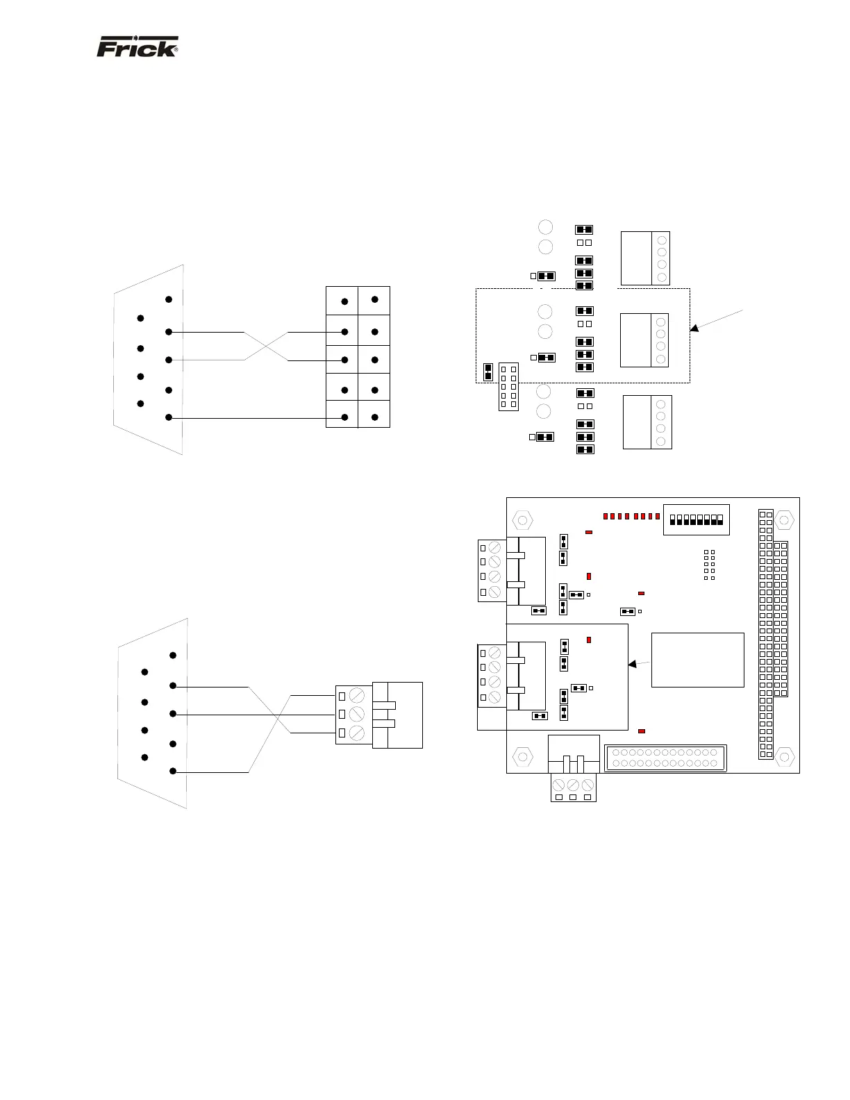
Following is the pin connections showing how to wire a
standard 9-Pin RS-232 connector directly to the 10-Pin
RS-232 connector on the Quantum™ 3, and the 3-pin
connector on the Quantum™ 4:
QUANTUM™ 3
Reference the drawing of the main processor board for the
location and positioning of the 10-Pin RS-232 connector.
Following is the pin positions of the 10-Pin connector:
Note: The TX2 and RX2 are I/O communication activity
lamps on the Quantum™ Main Processor Board that can
be monitored to see if the Com-2 port is receiving (RX2)
and transmitting (TX2) data.
QUANTUM™ 4
Reference the drawing of the main processor board for the
location and positioning of the 3-Pin RS-232 connector.
Following is the pin positions of the 3-Pin connector:
Converting an RS-232 Serial Port to RS-422 or
RS-485
In order to communicate to the Quantum™ controller via
RS-422 (or RS-485), you will need to convert the RS-232
signal from the source.
One converter that has proven to be effective is the Opto-
22 AC7A/B card. This card will allow the conversion from a
standard RS-232 signal to either RS-422 or RS-485. The
AC7A card is powered from a 115 VAC source, while the
AC7B card is powered from a 220 VAC source. They can
be used in a standalone panel along with an Allen Bradley
SLC 5/04 or along with an external modem. Keeping the
jumpers installed the same way they are received from the
factory, it is easy to wire for either RS-422 or RS-485.
NOTE: Refer to the manual that comes with the AC7A/B
card for specific jumper information (as the configuration
shown is only a suggestion that has worked in most
applications).
Once jumpers on the converter card have been verified,
you will need to verify the jumper settings of the
Quantum™ controller. Refer to the following diagrams for
the Quantum™ 3 and Quantum™ 4:
Quantum™ 3
Quantum™ 4
NOTE: Some of these jumper settings may need to be
modified to ensure optimum communications
performance. Typically, the termination jumper should be
installed in the last Quantum™ in the communications
daisy chain only (Link 7 for the Quantum™ 3, Link 1 for
the Quantum™ 4).
RX3
LK15
LK14
LK18
LK13
LK11
LK12
TX3
1 2 3 4
B
A
Verify the
umpers in this
location.
COM-2
RS-422/RS-485
LK17
TX2
RX2
COM-2
RS-232
B
A
LK19
COM-1
RS-422/RS-485
1 2 3 4
1 2 3 4
LK10
LK9
LK8
LK6
LK7
LK5
LK4
LK16
LK3
LK2
TX1
LK1
RX1
B
A
COM-3
Future Use
TXD
RXD
COM
9-Pin
Connector
1
6
2
7
3
8
4
9
5
3
1
Quantum™ 4
3-Pin Connector
COM
TXD
RXD RXD
TXD
TXD
COM COM
9-Pin
Connector
1
6
2
7
3
8
4
9
1 2
10
Quantum™ 3
10-Pin Connector
TB1
TB2
TB3
PL1
LK1
LK6 LK5
LK4 LK3
LK17
B
A
PL2
O
DIP
1 2 3 4 5 6 7 8
SW1
LK10 LK9
LK8 LK7
LK16
LK11
B
A
PL3
PL4
D3
D2 D1
D6
D8
0
1
2
3
4
5
6
7
PORT
D4
D5
D7
D8
D10
D11
D12
D13
Verify the
jumpers in this
location.
4 3 2 1
4 3 2 1
3 2 1
COM-1
RS-422
RS-485
COM-2
RS-422
RS-485
COM-2
RS-232