S90-010 CS (APR 08) FRICK
QUANTUM™ COMPRESSOR CONTROL PANEL
Page 6 COMMUNICATIONS SETUP
After verifying both the Converter card and Quantum™
jumper settings, the interconnecting wiring must be done.
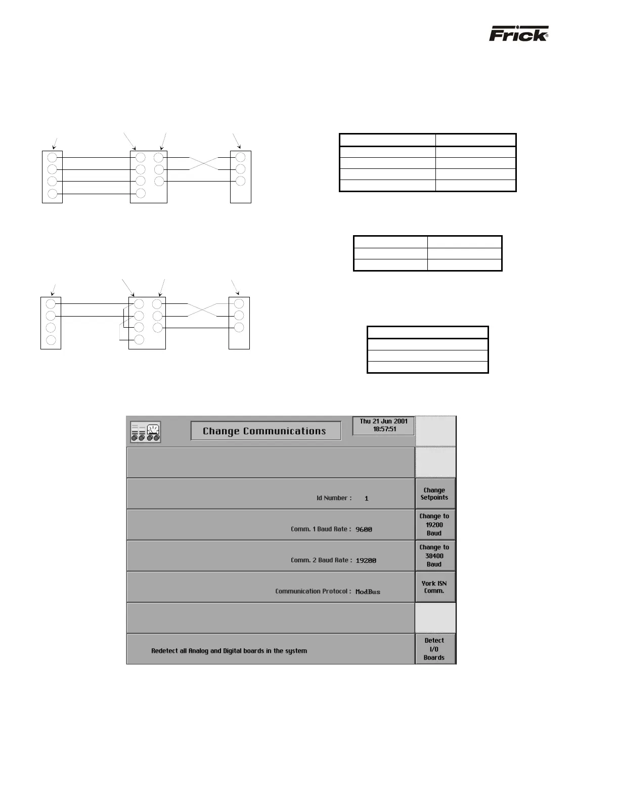
Be sure to use 4-conductor shielded communications
cable (two wires for transmit, two for receive). Refer to the
following diagrams for RS-422 and RS-485:
RS-422
RS-485
We have used both an Opto 22 AC7A/B and an Opto 22
AC422 adapter card. They can be wired to use either RS-
422 or RS-485.
Following is the pin connections showing how to wire a
DB9 connector on this adapter card to the Quantum™ for
RS-422 communication:
Quantum™ COM-2 DB9
1 5
2 4
3 9
4 8
Following is the pin connections showing how to wire for
RS-485 to the terminal connections on this adapter card
from the Quantum™:
Quantum™ Terminal
1 (-RX/-TX) FO-
2 (+RX/+TX) TO+
The card can be connected RS-232 to another device.
Following is the pin connections showing how to wire the
25-Pin RS-232 connector on this adapter card to a 9-Pin
connector of the SLC 5/04:
DB9 DB25
5 7
2 3
3 2
Change Communications
This screen is accessed by pressing the [Change
Comms.] key on the Panel Setup screen.
The following information is shown here:
• ID Number
• Comm. 1 Baud Rate
• Comm. 2 Baud Rate
• Communication Protocol
CTS
RXD
TXD
TO-
TO+
FO-
FO+
2
3
5
RS-232
Computer
Port
RXD
TXD
RTS
AC7A
RS-422 To RS-232
Converter
3
7
2
1
2
3
4
Quantum
™
COM-2
-RX
+RX
-TX
+TX
9-Pin Female
connector
25-Pin Male
connector
4-Pin
connector
Hard wire
CTS
RXD
TXD
TO-
TO+
2
3
5
RS-232
Computer
Port
RXD
TXD
RTS
AC7A
RS-485
To RS-232
Converter
3
7
2
1
2
3
4
Quantum
™ COM-2
-RX/-TX
+RX/+TX
9-Pin Female
connector
25-Pin Male
connector
4-Pin
connector
Hard wire
FO-
FO+