S90-010 CS (APR 08) FRICK
QUANTUM™ COMPRESSOR CONTROL PANEL
Page 68 COMMUNICATIONS SETUP
SETTINGS – CONTINUED
Frick
®
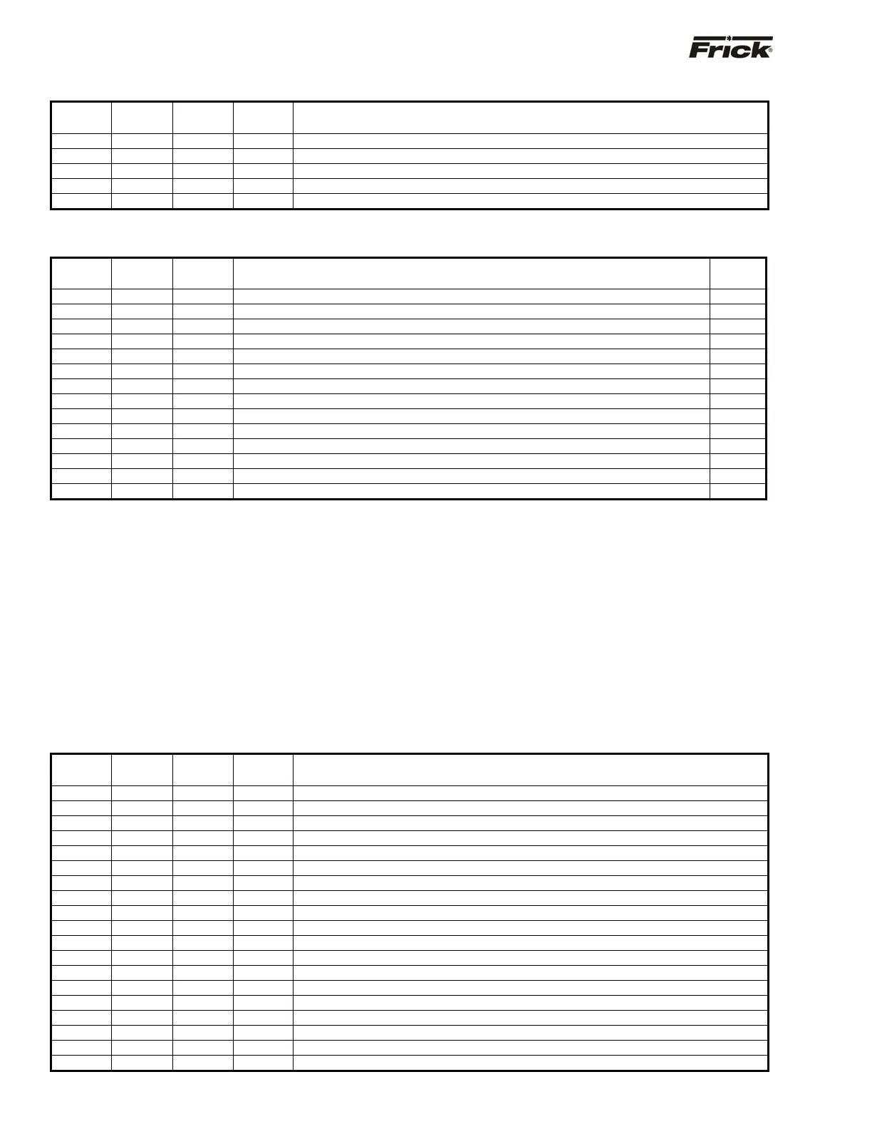
Address
AB
Address
Modbus
Address
Read
Only
Description of Data
1448 N24:148 41449 Economizer
ressure set
oint for Vi correction
1449 N24:149 41450 RDB com
ressor t
e Forced Unload Dela
1450 N24:150 41451 X Economizer
ressure in
ut mode
0=Disabled 1=Set
oint 2=Auxiliar
Ch.#10
1451 N24:151 41452 Atmos
heric Pressure at com
ressor site
1453 N24:153 41454 X VariS
eed Humidit
Control Enable
COMMANDS: (Write Only)
Modbus
Address
AB
Address
Modbus
Address
Description of Command
Ignored
Values
5000 N55:0 45001 Start/Sto
Com
ressor 0 = Sto
, 1 = Start
0&
1
5001 N55:1 45002 Load Command Pulse
Seconds
<=0
5002 N55:2 45003 Unload Command Pulse
Seconds
<=0
5003 N55:3 45004 Set Com
ressor Mode 0 = Manual 1 = Auto, 2 = Remote
1 &
2
5004 N55:4 45005 Slide Valve Mode 0 = Manual 1 = Auto, 2 = Remote
1 &
2
5005 N55:5 45006 Clear Alarms 0 = Clear for Modbus, 1 = Clear for Allen-Bradle
0 &
1
5006 N55:6 45007 Clear Remainin
Rec
cle Dela
time 0 = Clear for Modbus, 1 = Clear for A-B
0 &
1
5007 N55:7 45008 Com
ressor Se
uence 0 = De-Activate, 1 = Activate
0 &
3
5008 N55:8 45009 Ca
. Cont. Selection
see Fric
address 103 for values and Note 3 for chan
in
<0 or >7
5009 N55:9 45010 Setback 0 = De-Activate, 1 = Activate
0 &
1
5010 N55:10 45011 Condenser 0 = Not Active, 1 = Active Alwa
s, 2 = When Runnin
<0 or >2
5011 N55:11 45012 Remote Control Set
oint 0 = Disable, 1 = Enable
0 &
1
5012 N55:12 45013 Pressure & Tem
erature Units select 0 = PSIA, De
. C. , 1 = Panel setu
0 &
1
5013 N55:13 45014 Data values select 0 = x10, 1 = x100
0 &
1
Note 1: The compressor must be in remote to accept the start and stop commands that are sent through serial
communications, and the Slide Valve must be in remote to accept load and unload commands that are sent.
Note 2: The Compressor sequence De-Activate command that is sent through communications will only work if the
Compressor sequence Activate command was last sent through communications.
Note 3: A Capacity Control can only be made Active if it was enabled for capacity control and Setback is not Active and Input
Module Capacity Control is not enabled.
Note 4: A write message for more than one element is allowed for the Allen Bradley N55:0 address. A maximum size of 14
elements can be written to. An invalid setting sent with a Write Message is ignored.
Note 5: Command Values need tenths field added. For example, to start the compressor, the table above states that 1 = Start.
However, being that one decimal place is assumed, a value of 10 actually needs to be sent.
SPECIAL:
Frick
®
Address
AB
Address
Modbus
Address
Read /
Write
Description Of Data
2500 N25:0 42501 Read Alarm list
See Followin
Note 1 Below
2501 N25:1 42502 Read Run Time Hours
See Followin
Note 2 Below
2600 N25:100 42601 Read Run Time Hours
Hi
h Order 1000’s
2601 N25:101 42602 Read Run Time Hours
Low Order 1000’s
2602 N25:102 42603 Read Alarm # 1 Messa
e
Most Recent
2603 N25:103 42604 Read Alarm # 1 Hrs.
2604 N25:104 42605 Read Alarm # 1 Min.
2605 N25:105 42606 Read Alarm # 1 Date Hi
h Order
2606 N25:106 42607 Read Alarm # 1 Date Low Order
2607 N25:107 42608 Read Alarm # 2 Messa
e
2608 N25:108 42609 Read Alarm # 2 Hrs.
2609 N25:109 42610 Read Alarm # 2 Min.
2610 N25:110 42611 Read Alarm # 2 Date Hi
h Order
2611 N25:111 42612 Read Alarm # 2 Date Low Order
2612 N25:112 42613 Read Alarm # 3 Messa
e
2613 N25:113 42614 Read Alarm # 3 Hrs.
2614 N25:114 42615 Read Alarm # 3 Min.
2615 N25:115 42616 Read Alarm # 3 Date Hi
h Order
2616 N25:116 42617 Read Alarm # 3 Date Low order