12
Wall Controller Wiring Installation
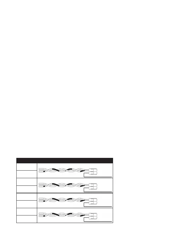
VRP Wiring Installation (Wall Unit to Lever Connector)
Connection 1: Insert the Orange (V+) wire from the Wall Controller into a lever
connector slot and close the orange lever on the connector.
Insert the twisted Orange and Green/White Cat 6 wires into the remaining lever
connector slot and close the orange lever on the connector.
Connection 2: Insert the Brown (D+) wire from the Wall Controller into a lever
connector slot and close the orange lever on the connector.
Insert the twisted Brown and Blue/White Cat 6 wires into the remaining lever
connector slot and close the orange lever on the connector.
Connection 3: Insert the Blue (D-) wire from the Wall Controller into a lever
connector slot and close the orange lever on the connector.
Insert the twisted Blue and Brown/White Cat 6 wires into the remaining lever
connector slot and close the orange lever on the connector.
Connection 4: Insert the Green (V-) wire from the Wall Controller into a lever
connector slot and close the orange lever on the connector.
Insert the twisted Green and Orange/White Cat 6 wires into the remaining lever
connector slot and close the orange lever on the connector.
WIRE COLOR LABEL
Blue
Connection 1
V+
Red
Brown/White
Green
Connection 2
D-
Blue
Orange
White/Green
Connection 3
D+
Brown
White/Orange
White/Blue
Connection 4
V-
Green
Brown