11
Wall Controller Wiring Installation
General Connection Procedure:
1. Remove 2” of the outer sheath of the
CAT6 cable (not supplied) including
the shield and strip the wires.
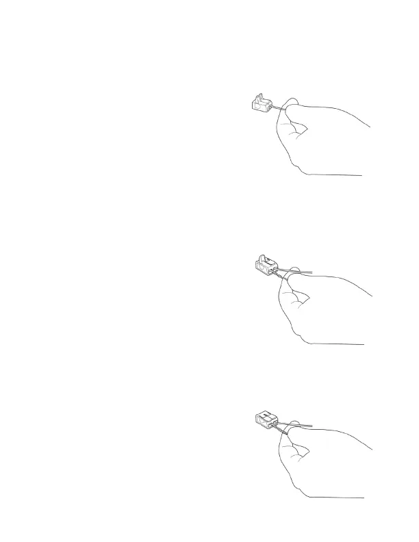
2. Insert the speci ed wire from the
Wall Controller into a slot of the lever
connector as shown in Figure 3 and
close lever as shown in Figure 4.
3. Insert the twisted wires from the
CAT6 cable into the remaining lever
connector slot as shown in Figure 4.
Each twisted, paired wire should be
inserted into its own separate slot in
the lever connector.
4. Close the orange lever on the lever
connector as shown in Figure 5.
Make sure the levers seat properly.
Figure 3.
Figure 4.
Figure 5.