Installation
Assembly work
Fröling Heizkessel- und Behälterbau Ges.m.b.H, Industriestrasse 12, A-4710 Grieskirchen Page 19
Tel +43 (0) 7248 606-0 Fax +43 (0) 7248 606-600 info@froeling.com www.froeling.com
M1010108_en
3
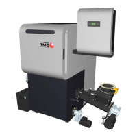
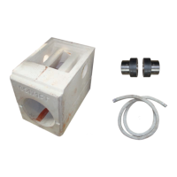
Screw set
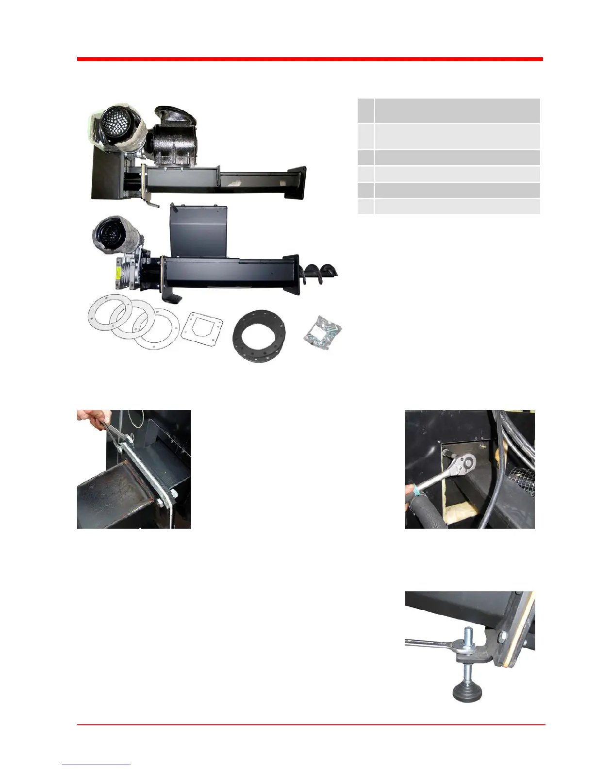
The following steps will guide you
through the assembly process when
installing a G30 stoker.
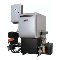
If you are using a G50 stoker, the
connection flange comes out of the
insulation (see image on left).
The assembly steps apply by analogy in
the same order.
Assembly G50 stoker
U Attach seal for stoker duct and fit
stoker unit
U Screw in carrying bolt on stoker
flange and tighten
Assembly G30 stoker
A
B
E
 Loading...