160
Measuring welding circuit resistance r
General Measuring the welding circuit resistance “r” makes it possible to have a constant welding
result at all times, even with hosepacks of different lengths. The welding voltage at the arc
is then always precisely regulated, regardless of the length and cross-sectional area of the
hosepack. Adjustment using the arc length correction parameter is no longer necessary.
The calculated welding circuit resistance is displayed on the right-hand digital display.
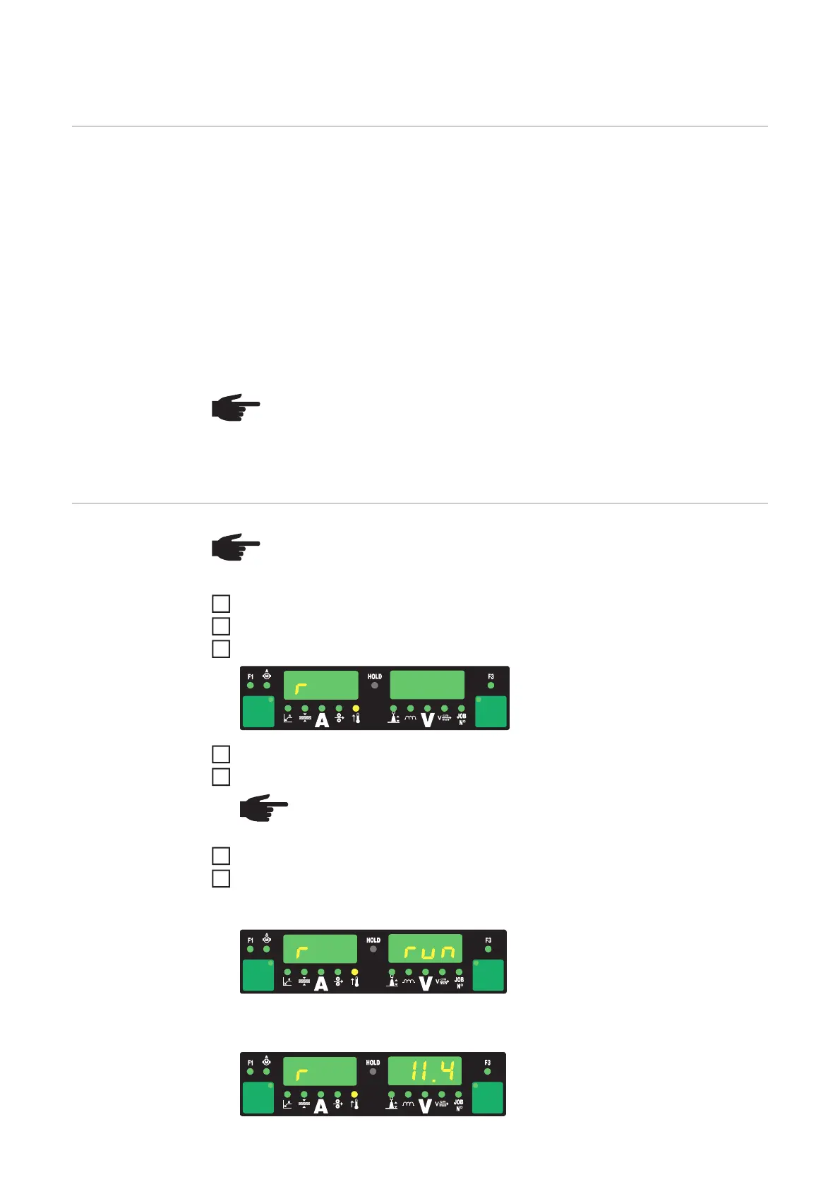
r ... Welding circuit resistance (in m)
If the welding circuit resistance r has been measured correctly, the welding voltage will cor-
respond exactly to the welding voltage at the arc. If you manually measure the voltage on
the output jacks of the power source, this voltage will be higher than the welding voltage at
the arc - that is, higher by the same amount as the voltage drop of the hosepack.
Measuring weld-
ing circuit resist-
ance r
Make a ground (earth) connection to the workpiece
Open the Setup menu - level 2 (2nd)
Select parameter “r”
Remove the gas nozzle from the welding torch
Screw on the contact tube
Place the contact tube down firmly on the surface of the workpiece
Briefly press the torch trigger or the Feeder inching button
The welding circuit resistance is calculated. During the measurement "run" is dis-
played on the right-hand digital display.
The measurement is finished when the welding circuit resistance is shown on the
right-hand digital display (e.g. 11.4 m)
NOTE! The welding circuit resistance r depends on the hosepack used:
- if the hosepack length or cross-sectional area is changed, measure the weld-
ing circuit resistance r again
- measure the welding circuit resistance for each welding process separately
with the appropriate welding leads
NOTE! In order to obtain good welding results, it is essential to measure the weld-
ing circuit resistance correctly. Make sure that the contact between the earthing
clamp and the workpiece is on a cleaned workpiece surface.
1
2
NOTE! Make sure that the contact between the contact tube and the work-
piece is on a cleaned workpiece surface. While the measurement is being
performed, the wire-feed unit and the cooling unit are deactivated.
4
5
6
7
 Loading...