39
EN
NOTE! The functions available on the control panel of system compo-
nents are restricted in the same way as those on the control panel of the
power source.
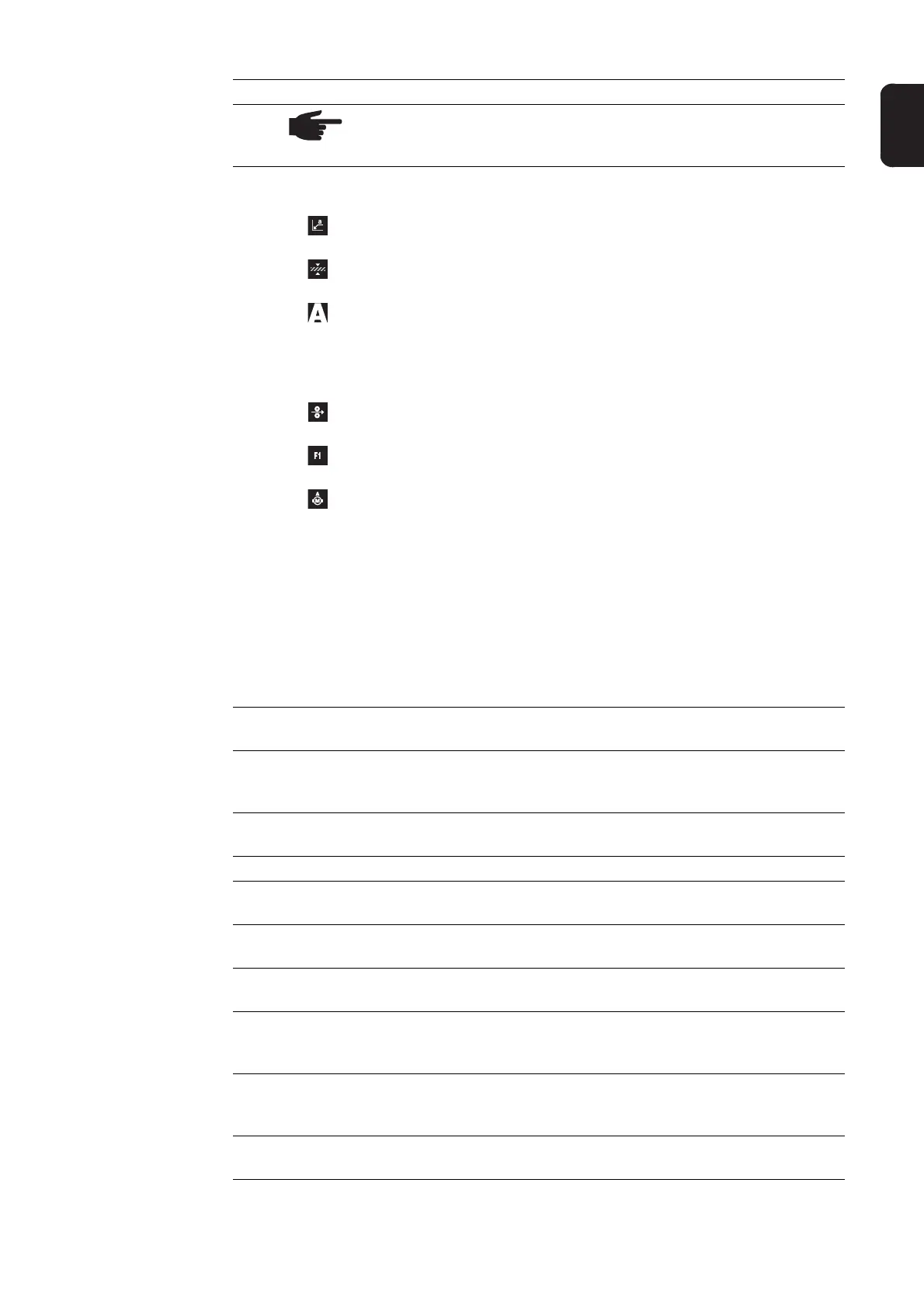
(3) Parameter selection button
for selecting the following parameters:
a-dimension
1)
Dependent on the set welding speed
Sheet thickness
1)
Sheet thickness in mm or in.
Welding current
1)
Welding current in A
Before the start of welding, the machine automatically displays a stand-
ard value based on the programmed parameters. During welding, the
actual value is displayed.
Wire feed speed
1)
Wire feed speed in m/min or ipm.
F1 indicator
indicates that the current-input PushPull drive is switched on
Wire-feed rate drive current-input indicator
indicates that the wire-feed rate drive current-input is switched on
If the indicators are lit up on the parameter selection button (3) and on the adjust-
ing dial (21), then the indicated/selected parameter can be altered using the ad-
justing dial (21).
1)
The synergic function means that if one of these parameters is selected
during MIG/MAG pulse synergic welding or MIG/MAG standard syner-
gic welding, then all other parameters including the welding voltage pa-
rameter are automatically set as well.
(4) F1 indicator LED
lights up when the F1 indicator parameter is selected
(5) Wire-feed rate drive current-input indicator LED
lights up when the wire-feed rate drive current-input indicator parameter is select-
ed
(6) a-dimension LED
lights up when the a-dimension parameter is selected
(7) Left digital display
(8) Sheet thickness LED
lights up when the sheet thickness parameter is selected
(9) Welding current LED
lights up when the welding current parameter is selected
(10) Wire feed speed LED
lights up when the wire feed speed parameter is selected
(11) Overtemperature indicator
lights up if the power source overheats (e.g. because the duty cycle has been ex-
ceeded). For more information on this, see the "Troubleshooting" section.
(12) HOLD indicator
every time a welding operation finishes, the actual values for welding current and
welding voltage are stored, and the HOLD indicator lights up.
(13) Arc length correction LED
lights up when the arc length correction parameter is selected
No. Function
 Loading...